

Hey Guys, hopefully someone here can help me. I am inching towards getting one of my xenon short arc lamps running and I got my hands on one of the HV exciters. I opened it up and got some pictures for you guys as well I drew up a schematic to the best of my knowledge.
Hopefully someone here can give me a better idea on how it works.
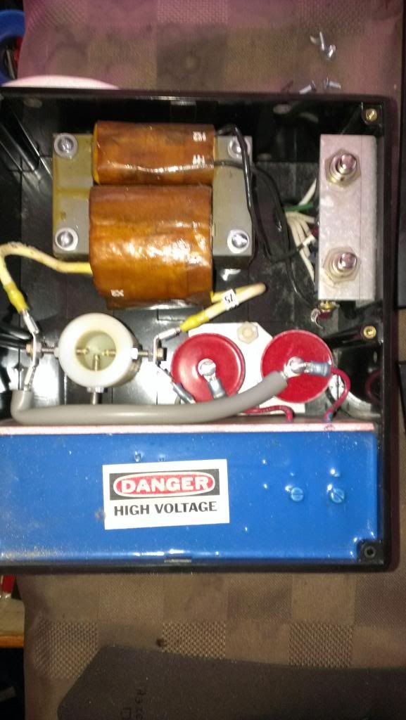
Before I get to the pictures, the whole system is out of a theater projector which is automated. , in the first picture you can see 2 push button switches in the top right corner. the one right in the corner is i presume a safety as the lid holds it down. The other switch has a cutout in the lid and if the bulb didn't ignite we could manually ignite using that switch.
Can anyone tell me what might be in the blue section?
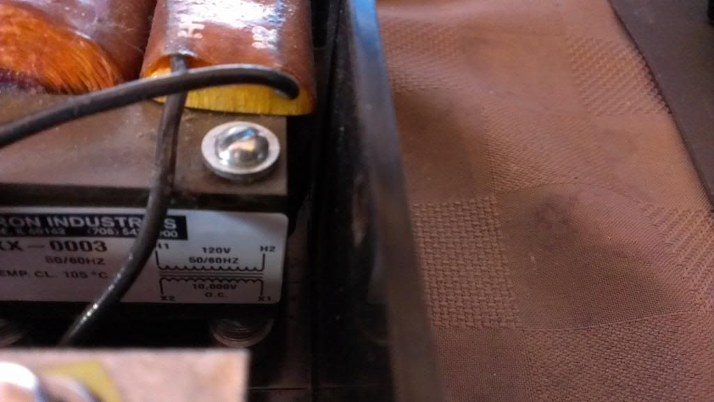
Transformer information
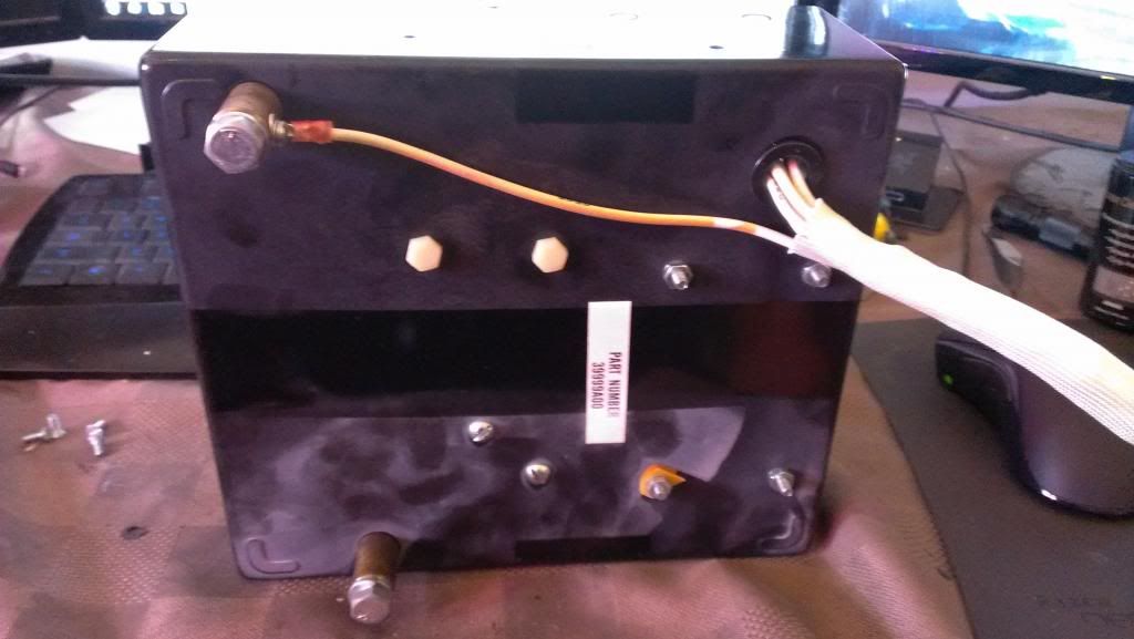
Underside: those re the 2 terminals coming out from under the blue box that wire attached, do you think that is a signal wire or does it serve another purpose? (it is attached to the negative side of the rectifier)
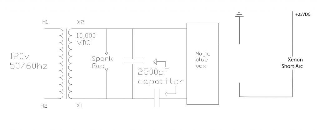
Schematic: (forgive the misspelling)
So, the white wires you see coming out the bottom all attach to the 2 switched and I assume they are for the automation/manual use of this device one thing to note is inside the lamphouse this came from there was bank of terminals that the switched were attached to which I believe at least some went to the rectifier some of those had small ceramic disc capacitors attached to them. are they important or do you think they were just to filter the lines?
AND, the most important question (YES I WORK SAFELY) if I were to wire up the transformer, would I get sparks out the other side or am I missing something?
Thanks Guys!
Hopefully someone here can give me a better idea on how it works.
Before I get to the pictures, the whole system is out of a theater projector which is automated. , in the first picture you can see 2 push button switches in the top right corner. the one right in the corner is i presume a safety as the lid holds it down. The other switch has a cutout in the lid and if the bulb didn't ignite we could manually ignite using that switch.
Can anyone tell me what might be in the blue section?
Transformer information
Underside: those re the 2 terminals coming out from under the blue box that wire attached, do you think that is a signal wire or does it serve another purpose? (it is attached to the negative side of the rectifier)
Schematic: (forgive the misspelling)
So, the white wires you see coming out the bottom all attach to the 2 switched and I assume they are for the automation/manual use of this device one thing to note is inside the lamphouse this came from there was bank of terminals that the switched were attached to which I believe at least some went to the rectifier some of those had small ceramic disc capacitors attached to them. are they important or do you think they were just to filter the lines?
AND, the most important question (YES I WORK SAFELY) if I were to wire up the transformer, would I get sparks out the other side or am I missing something?
Thanks Guys!

