Welcome to Laser Pointer Forums - discuss green laser pointers, blue laser pointers, and all types of lasers

Buy Site Supporter Role (remove some ads) | LPF Donations

Links below open in new window

FrozenGate by Avery

Help request for replacing a laser diode assembly

Re: Help request for replacing a laser diode assem

It should hook up the same way as your other diode, but in case it doesn't there should be a datasheet available on the site you purchased it from that will show pinout. Typically those types of diodes are case-pin negative.. This means that the diode case itself is the negative terminal. The other two pins are the laser diode , and the photodiode (this is usually not used, it is used to sample the output and feed a circuit that controls current. This adds stability, but is most likely not used in your installation..) The case being negative means you just need to know which pin is the laser diode and apply the positive voltage there. But as I said, it really should be as simple as connecting the diode the way it originally was...


Re: Help request for replacing a laser diode assem

The diode datasheet is here http://stonetek.org/shop/images/808_200.jpg which Greg says is lacking, but I don't have a clue how to read the schematic part of it. Unfortunately the old diode had only two pins, neither of which was originally hooked up, but both had solder and wire bits as if they had been. The new diode has three, so I'm still at a bit of a loss. :'(
 
Re: Help request for replacing a laser diode assem

Picture the back of the diode. According to the datasheet, pins 1&2 are the ones you're interested in. Pin 2 (the one that connects directly to the can, usually the middle one) is negative. Pin 1 is positive.  

3  . .  1

.  2

This simple diagram describes the pins as viewed from the back of the diode.

Pin 1 gets +, pin 2 gets - , pin 3 is not connected to anything.

Hope this helps.


EDIT for typo
 
Re: Help request for replacing a laser diode assem

:o :o I happened t reread your last post, and I noticed you said the old diode wasn't originally hooked up? This may be a dumb question, but there's no chance that may be the reason it stopped working, is there??
 
Re: Help request for replacing a laser diode assem

OK, starting to make more sense now.  I looked at another spec sheet for one of stonetek's other diodes (it was a clear pdf so much easier to read), and I see where the diagram shows common being at the "point" of the triangle and anode being the base, and I see that same sort of diagram in the jpg for my LD.  But arent the pins numbered like this?

3 .        . 1
     .2

But still 1 & 2 being the important pins?  2 being + and 1 being -?

The diagram you posted looks like the Sony 16X spec sheet, which was the pdf I mentioned above.  But the important pins there are 1 & 3.

So what happens if I hook this thing up wrong?  Nothing, LD fries or black hole swallows the earth?  :)

Sorry, its late, and I'm nor sure if the above makes sense, I'll read again tomorrow, but I already typed it, so might as well post it.
 
Re: Help request for replacing a laser diode assem

Sorry about the typo... long day :-/ :-/


I'll go ahead and start spreading the word about the possible singularity problem, wouldn't want everyone to get gulped up into a black hole with no warning...
 
Re: Help request for replacing a laser diode assem

For 808nm diodes.

1 is -
2 is + (also ground)
3 is feedback or nothing
 
Re: Help request for replacing a laser diode assem

Ya know not to sound disparaging but with an output of only 5mw on that laser, it seems like a lot of work and a lot of $$ when it could very easily be replaced with a different laser. Your photos don't really give a good example of size in relation to other known things so it's hard to really determine that the diode is truly a 9mm. does your "adapter" fit? It's my thinking that you could easily find a laser of similair power and functionality (blanking and ttl) that will allow you to easily incorporate the new laser into your unit. Just my $.02

I do however like that setup and there is a possibility that those crystals are capable of putting out more power than the 5mw you were getting before. TBH this looks like a project I'd love to dig my hands into and beef up and make a MUCH more impressive show out of.
 
Re: Help request for replacing a laser diode assem

Kenom's right about the potential to beef up that system. Also, looking back at the original pictures, I notice that this might be a discrete system. It seems that in your laser the two types of crystals that are used to make green could be separate from one another instead of "microchip" or DPM lasers that have the two crystals glued together to form one small crystal. I say could be because I can't really see everything from those angles. This is a really good thing if true. Discrete crystals have potential for higher output because of their relative size compared to DPMs but also comes with the burden of extremely sensitive alignment compared to DPMs. Yours are obviously fully prepared and aligned since they are installed in a mostly usable laser cavity which means you could, theoretically, get a higher powered pump diode and get proportionally higher 532nm output as a result. (within reason)
 
Re: Help request for replacing a laser diode assem

there are a lot of source for 200-250 mw 9 mm diodes on ebay

However for the price of a diode u can also almost buy a complete 50 mw green laser module (60 dolars)
 
Re: Help request for replacing a laser diode assem

Kenom said:
Ya know not to sound disparaging but with an output of only 5mw on that laser, it seems like a lot of work and a lot of $$ when it could very easily be replaced with a different laser.... TBH this looks like a project I'd love to dig my hands into and beef up and make a MUCH more impressive show out of.

Oh I most certainly have ideas floating around in my head of doing that, but I figured for $12 I couldn't resist fiddling around with it just to see what would happen.  The adapter does fit the barrel of the casing, and the small diode will fit inside the adapter.  I plan on taking some careful measurements as to the distance from the crystal to the original diode and try to match that with the new setup.  Hopefully I haven't fried the driver as I powered up the system with no laser in it to test for voltage at the laser output pins, and to check the operation of the apertures via DMX control.

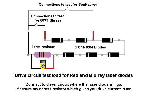
On a different note, I had posted in another category about a dummy load for a green laser.  The answer was that it is really for a IR laser, because that is what drives the green.  rog8811 posted that he thought it would take less than 4 1N4001 diodes, but I never got a reply as the reasoning behind less diodes.  Anybody can point me to a primer on how the dummy load works?  I would like to load the driver to check output before I actually hook up a LD to it.  I'm guessing  it should be set to output around 200mw to drive the IR LD (which is what the LD is rated at).

Oh, and as far as a size reference, the overall length of the assembled body is about 3.5-4" with a diameter of about 3/4" (just guessing.)
 
Re: Help request for replacing a laser diode assem

Here's the standard dummy load circuit:

test_load01_002.jpg


For an IR diode you should only need 2 1N4001 diodes instead of 4 or 6. With standard 1N4001 diodes, current will not flow through the diode until the voltage is above 0.7V. If you have 2 diodes in series (like they are in the schematic), then current will not flow until the voltage across the diodes is 1.4V. In other words, the voltage required for current to flow depends on the number of diodes that are connected in series. Since IR laser diodes usually require less than or equal to 2V to operate, you'll need 2 diodes. Once the current is flowing through the dummy load, then you can take a voltage reading across the 1-ohm resistor with a multimeter. The reading will be in mV. This mV reading corresponds to the number of mA that the driver is supplying. If the reading it 100mV, then the driver is supplying 100mA of current.

Hope this helps..
 
Re: Help request for replacing a laser diode assem

Since IR laser diodes usually require less than or equal to 2V to operate
Ah now that is interesting, I wrote in the other thread...
This may help with your original question
As I need to test a greenie circuit, the IR LD's usually run @ 2.5v so I will try 3 diodes @ 0.7 = 2.1v

I was only guessing at the voltage from memory as I could not find any info on it, thanks for the info EF

*note to self* I must start signing my schematics so people know who drew them.... ::)

Regards rog8811
 
Re: Help request for replacing a laser diode assem

All due credit to rog8811 on the schematic.. sorry, if I'd known that was yours I'd have said that in the first place.. As for the voltage, I believe that it is the same across all 808 diodes, but I based that on assumption since my c-mounts usually seem to like anywhere between 1.8-2.1V for best results, but I know that most datasheets list absolute maximum voltage as 2.4V... Anywhere in that range is fine in my experience.. but take me with a grain of salt, since i seem to keep writing everything backwards these last few days... I'd look it up for sure if I had more time, but the last few days have been absolutely a nightmare for me. Let's just say a GM dealership forgot to put 3 quarts of oil in my car. can you say "oops"...
 
Re: Help request for replacing a laser diode assem

Hmmm, so the data sheet for my replacement LD says 2.3V max and 1.9V Tty (Typical?).  The laser output pins on the built-in board I've got was reading about 3.1V with no load.  I'm thinking I will fry the LD if I hook it up to that, yes?
 
Re: Help request for replacing a laser diode assem

You have to take measurements under load. The output parameters change while under load. You should see a reading that better matches what you need. That's the purpose of a dummy load..


Back
Top