Welcome to Laser Pointer Forums - discuss green laser pointers, blue laser pointers, and all types of lasers

Buy Site Supporter Role (remove some ads) | LPF Donations

Links below open in new window

FrozenGate by Avery

Help need to identify TTL ( + ) and ( - ) ...

emilvv

0
Joined
May 6, 2018
Messages
5
Points
0
Hello from Bulgaria, Europe,

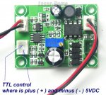
I have two 405nm lasers with this TTL drivers, but on the PCB TTL ( + ) and ( - ) are not marked ...

Please, if you know where they are - attach the image with correct labeled + and - of TTL control ...

or give an idea how to find them .. :)

THANK YOU in advance,

Emil
 

Attachments

  • 800600.jpg
    800600.jpg
    111.7 KB · Views: 36


An introduction in the welcome section is usually your first post, not this. I am guessing when you try to contact the seller in China, they don't know, don't understand or don't reply?
 
Last edited:
Hi,

I post welcome message ... :)

I tryed to ask china aliexpress store ... but no answer ... yet .

Also browse many google pictures for laser drivers ... all like mine with no TTL schematic .. :(

Regards,

Emil
 
Can you turn the circuit board over and take a photo of the traces? Can you give us a link to the product you purchased?

E: I can guess, but I could also guess wrong, need to see more. Is the upper trace isolated from foil ground, or do both contacts have individual traces and where do they go? Looks like each pin has its own trace and not part of the -12 VDC ground, which would make sense.
 
Last edited:
I can guess lower one is probably positive, but that is only due to the others being that way, if red represents positive. I'd wait for an answer from them, hopefully they have a drawing. You could also search ebay or aliexpress to see if another seller might be selling the same thing and provide a schematic in the listing, or just ask them for help too, some might, even if you didn't buy it from them in the hope of future business.
 
Check to see if one of the TTL pins is connected to
the Black Power pin with a DMM.
If so... that is your TTL negative.
If no common ground connections then wait for the
seller.
Since I can't see the bottom of the PCB.. I have no
perfect solution.

Jerry
 
Last edited:
I was wondering if the negatives were connected together as a common or not, but if they are, that would sure indicate it is the negative, duh...
 
Hello,

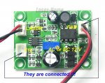
I checked the FAN ( - ) and it is connected to one of the TTL pins - as attached image ... Is it the TTL pin ( - ) ?? :)

Also .... attached TTL cable ( from my aliexpress order ... ) is with BLACK and RED wires .... and black is exactly to let say ( - ) TTL pin on the PCB .... :) ....

Regards,

Emil
 

Attachments

  • 0.jpg
    0.jpg
    117.1 KB · Views: 20
Last edited:
Hello,

I checked the FAN ( - ) and it is connected to one of the TTL pins - as attached image ... Is it the TTL pin ( - ) ?? :)

Also .... attached TTL cable ( from my aliexpress order ... ) is with BLACK and RED wires .... and black is exactly to let say ( - ) TTL pin on the PCB .... :) ....

Regards,

Emil
Obviously......:wtf::yh:

Jerry
 
TTL inputs are typically very low current. Does the laser come on without anything connected to the TTL input? If so, try shorting the two pins together to see if it goes out. It should. Now if all this is confirmed, you only need to apply a short across the pins to control the TTL. Do you see where I am going with this?
 
Boy this driver looks very familiar. I believe I had one of these back in 2010, to drive a 300mW LPC826 (660nm).
The fellow selling them was from Seoul. As stated above the method of using a DMM to find the TTL polarity is what I used back in the day.
So I recommend following this.


Back
Top