Welcome to Laser Pointer Forums - discuss green laser pointers, blue laser pointers, and all types of lasers

Buy Site Supporter Role (remove some ads) | LPF Donations

Links below open in new window

FrozenGate by Avery

Heatsinking

Morgan

0
Joined
Feb 5, 2009
Messages
2,174
Points
0
Hi All,

I've been wondering for a while and now I'm looking at a build for which I will need some bespoke heatsinking.

As I progress with my engineering course I am aware that there are formulae for working out how heat flows through different materials but my tutors are a little vague as to what they actually are!

Can anyone help with some, 'rules of thumb', or even a full explanation? How do IgorT, or Jayrob, or any of the other experienced builders calculate these things? (If anyone thinks they would like to be added to this list then I'll be happy to edit you in! :D )

I'm aware, so far, that material, (and how fast heat travels through it), mass and surface area all come together to show how big a heatsink should be. Further than that I am stumped as to where to start.

Any pointers will be handy.

Thanks,

M
:)


I'm rather confident that the host plays a role too.

Ideally the heat sink should fit the host and the diode / module well, remain attractive and do it's job.
 
Morgan;

Heat sinks will become more important as Laser diode power increases.

I have built several lasers for continuous-duty use.

Here is a photo of one 6X model with a heat sink that can handle 2.5-3 watts:
6xheatsink.jpg

The Aixiz module is pressed in with thermal compound.
Total thickness is ~ 5/8".

The entire host design can be seen on this thread:

http://laserpointerforums.com/f38/new-6x-continuous-duty-br-build-43433.html

It should be adequate for a 8X as well.

LarryDFW
 
Last edited:
That is a sharp looking sink, and see how it's engineered to fit the host as well.

Excellent!

Looks like aluminum, could also be anodized to many sharp looking colours as well.
 
Thanks guys,

For this build I will be looking for square heatsinks. Yes, square! I can get a rough idea of the size from seeing all the cool sinks made here, (and very nice they look too I may add), but I'm looking for more empirical data.

For example; If I want to use a 12mm dia, 100mW DPSS, 532nm module that produces 70degrees C surface heat without a heatsink. What mass of aluminium and what surface area would best to bring this down to 40degrees C with a constant duty cycle and no cooling fan at an ambient temperature of 21degree C?

I know that's a bit of complex material science request but I want to be able to prove the theory before resorting to trial and error.

Hope that narrows my request.

M
:)
 
The 'performance' of a heatsink is expressed as its thermal resistance, a value in K/W (or C/W, F/W if you must).

There are several factors that influence this performance, the most important is surface area / size. Usually heatsinks are designed with a number of fins, increasing the surface area compared to a solid block of equal size. This works to some degree, after which the fins get too thin to transport the heat along themselves (this is where thermal resistance of the material comes in).

Another factor is the precise shape, position and airflow around a heatsink. If you buy a heatsink with a specified K/W value, this is usually based on placement with the fins vertically, and unrestricted, unforced airflow.

To give a bit of an indication: a 1 K/W typical heatsink would be an array of fins, about 8 by 4 inches in size, with the fins a bit over an inch long. This would be a fairly bulky one, typically found in power audio amplifiers and such.

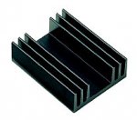
For cooling diode lasers, something in the order of 10 K/W could be accetpable (5 degree rise over ambient for 0.5 w of power). See the attached picture for a 10 K/W heatsink, it is roughly 1 x 1.5 inches in size, with about half an inch fins.
 

Attachments

  • heatsink.jpg
    heatsink.jpg
    8.8 KB · Views: 91
Btw, heatsinks come in all kinds of exotic shapes, but in practice this makes relatively little difference in performance. If you want to heatsink something round, it would be an obvious choice to have something where the fins radiate out from the laser module, but the size would still be comparable.
 
Thanks Benm, that's a really useful explanation. And now come a couple of inevitable questions... Sorry in advance!

To clarify the units of K/W... Where K is the temperature in Kelvin? And W is... ?

You also mention a typical 1 K/W being 8 inches by 4 inches, (or 203.2 x 101.6mm for us Brits! :p), with 1 inch fins. The picture you kindly showed was a 10 K/W sink but was considerably smaller. Is this a typo or am I missing something?

I'll try and do a calculation using the info but will probably fail so I may come back to you if you don't mind.

Thanks again,

M
:)
 
K is the difference from ambient temperature in Kelvin (or celcius, since its a difference it doesnt matter).

W is the power applied to the heatsink it watts.

A larger number in K/W means that a heatsink will get hotter for a given amount of power supplied to it, which is why the number in K/W gets bigger for smaller heatsinks.

For example, just the case of a LM317 voltage regulator (without any heatsink) has a thermal resistance of about 50 K/W. If you would require the regulator to stay under 75 degrees with 25C degrees ambient temperature, you could make it dissipate only 1 watt (resulting in 25C + 50K/1W = 75 C case temperature).

On the other extreme, a 0.1 K/W heatsink would probably be difficult to lift by hand, but would only warm up 10 degrees if you put 100 watts of power into it.
 
Ah, I see. That is clearer. So knowing the Thermal Resistance of a heatsink and any two of the other variables will give you the last one. Ok, I think I can grasp that one.

so, assuming I use something similar to the heatsink you showed, (10K/W), an ambient temperature of 25C and I want to limit to 40C the formula is therefore...

25 + 10K/xW = 40C
thus, x = 10/(40-25)
x = .666W

So I can dissipate 666mW, of heat, through that heat sink to maintain 40C? Is that right?

M
:)
 
Last edited:
Not exactly. You are willing to accept 15K of temperature rise. The heatsink will heat up 10 K for each watt, so 15/10 = 1.5 watts would be the maximum power... but thats just a matter of getting the numbers juggled i suppose.
 
Ok, thanks. I'll let that rattle around for a few days and do some more sums on paper when I have more time. I'll definitely be coming back to this one as my next problem will be to work out the power I need to dissipate from a given diode with a given setup. I understand P=IxV and think this is where I should start but how to include mW light output is unclear to me at the moment.

Thanks for your help so far and, if you're willing, I hope you can keep an eye out for more on this.

This has been educational so far....

M
:)
 
^Well your next part is the easiest: Power in = Power out.

Say you're running a diode at 6V and .4A, therefore you're putting 2.4W of electrical power into the diode. All that power has to come out, and in this case it comes out in (basically) 2 forms: light and heat. If you say there's 500mW (.5W) of light coming out, you have to dissipate 1.9W of heat coming out of the diode, since energy is conserved.

Make sense?
 
That is easy! Something simple for a change! Ya!

I'll continue on the research...

Thanks.

M
:)
 
The calculations are usually pretty simple. Most people in electronics calculate heat flows in a very similar fashion to current, voltage and resistance.

Mostly, you are working with a number of thermal resistances in series: from die/chip to its housing, from its housing to an aixiz module, from that to a heatsink, and from there to ambient.

One problem is that sometimes not all these resistances are known. Those from die to casing are usually specified by the manufacturer, but from there you can be on your own. With commonly used transistor cases and such, the values have been determined to some degree, but noone will specify the thermal resistance between a diode and an aixiz module. This is very hard to do, since it does depend on how well it fits exactly, if you use any thermal compound, and how hard you press it in.

Still, if you fit everything properly, the biggest resistance is from heatsink/host to ambient, at least in handheld devices. You can do fairly usable calculation assuming all contact resistance is zero down to heatsinks in the order of 10 K/W. Below that, they will become more important and must be accounted for.
 
... I said I'd come back to this one...

Ok, so I've let all this rattle around and had a chat with my lecturer. (We'll apparently be covering this in more depth in the near future and I've been handed an assignment too!)

Just to check with you all I'm getting this part, here's a question from the assignment and some other calculations:

"1. The circuit requires the transistor, (a TIP31A), to dissipate 2.5 watts of power, and the ambient temperature inside the product chassis is estimated to be 40 deg C.

Using thermal analysis techniques, calculate the junction temperature of the TIP31A transistor without any heat-sink applied."

Junc temp = amb temp + (Thermal/resistance total * Power dissipated)

Therefore, junc temp = 40 + (62.5, (found on the datasheet), * 2.5)

junc temp = 196.25 deg C.

Second part asks is this above absolute maximum and it is. Absolute Max is 150 deg C


I'm fairly sure I've got this right, (Not least for the help you guys gave me recently, I may add), but I seem to be falling down when I want to apply this to our mutual hobby.

Firstly, I can't find a max junction temperature value on a datasheet for the LOC, http://www.glyn.com/data/glyn/media/doc/ML101U29.pdf . It gives a max case temperature of 75 deg C so I've been using this but I am not confident this is correct.

Here's what I've worked out, (tried to work out), using easy figures from the datasheet above:

Power dissipated by an LOC = power in - light ouput. So if 205mA at 3V outputs 120mW we get, from P=IxV, (0.205 x 3) - 0.12 = 0.495W

If I want to keep the case temperature to 75 deg C in abient temp of 25 deg C, then using the formula in the assignment question I get:

75 = 25 + (thermal/resistance, (or x) X 0.495)
75 - 25 = x X 0.495
x = 50/0.495
x = 101 C/W? :thinking:

I don't get the high figure for the thermal resistance. 101 C/W is either really high, or I would only need a tiny heatsink. I know the powers we use are much higher so this would bring the figure down but am I going about this the right way? Is using 75 deg C from the datasheet as a junction temperature acceptable given no other info? Is my maths correct for a start?!

Yours,

confused, but hopeful,

M
:)


Back
Top