Welcome to Laser Pointer Forums - discuss green laser pointers, blue laser pointers, and all types of lasers

LPF Donation via Stripe | LPF Donation - Other Methods

Links below open in new window

ArcticMyst Security by Avery

General driver heatsinking tips (driver attached to host body or diode heatsink) ?

Joined
Jan 7, 2012
Messages
149
Points
18
The following questions are for using a large heatsink (e.g. host body or diode heatsink) for an SXD driver running at 4+ Amps:

1) Which component(s) of the driver needs to be heatsinked the most? What does that component look like on the board? Since many rectangular driver boards have components on both sides, which side needs to contact the heatsink (face down position) ?

2) If the driver has a potentiometer, is it best to keep the side of the board with the potentiometer face-up for future access to the potentiometer?

3) What is the best way to attach the heatsink (Arctic Silver or another brand)? Or holding the board down mechanically with a bar of some sort?

4) What areas of the board or components should be avoided when applying thermal glue? The legs of the CPU or the tracing on the board or.....?

5) Is it best to apply a thick layer or thin layer of thermal epoxy? I assume thicker means greater electrical insulation from the metal heatsink (good) but greater thermal insulation (bad)?

6) How do I electrically insulate the components of the board since they will be touching the metal heatsink? I think DTR uses a special thin tape ?

7) Has anyone experienced the driver 'popping off' from its location where it was bonded, after the thermal epoxy cured ?

8) What about thermal pads, clay, putty? Are they all the same thing? Has anyone experienced a blob of clay debonding and rattling around inside the host?

9) Is it better to have a driver heatsink which is separate from the diode heatsink so both are not contributing heat to the same heatsink?

10) How much of the total heat is generated at the driver vs. the diode?

11) What is the best way to attach a driver to the inner surface of the battery tube of the host (since the board is flat and the tube is curved)?

12) Generally, which comes first: attaching the leads to the driver or attaching the driver to the heatsink (for convenience and ease of
assembly) ?
 
Last edited:


Joined
Jan 29, 2014
Messages
12,031
Points
113
My answers:

The following questions are for using a large heatsink (e.g. host body or diode heatsink) for an SXD driver running at 4+ Amps:

1) Which component(s) of the driver needs to be heatsinked the most? What does that component look like on the board? Since many rectangular driver boards have components on both sides, which side needs to contact the heatsink (face down position) ?

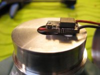
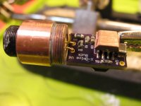
Just the main chip needs to be heat sinked, nothing else.

2) If the driver has a potentiometer, is it best to keep the side of the board with the potentiometer face-up for future access to the potentiometer?

Yes, but if you can't, see if you can make a hole through what ever it is mounted on to be able to adjust it. Worst case, if you cannot do that, adjust it before mounting but that is a no-brainer..

3) What is the best way to attach the heatsink (Arctic Silver or another brand)? Or holding the board down mechanically with a bar of some sort?

You can hold it down with a bar of some sort that is what I try, but if not, heat sink epoxy is what many use, I've used it and later wanted to reposition the driver and was able to pop the driver off with a screw driver anyway and file down the residual glue from the driver chip and reapply, but I suppose that depends upon how well it was glued and which brand of epoxy.

Photo of Arctic Silver products, two part epoxy and a compound which works well:


The two small tubes are epoxy, A and B. I turned one over to show the name.


4) What areas of the board or components should be avoided when applying thermal glue? The legs of the CPU or the tracing on the board or.....?

I would not allow excess glue to go anywhere if you can help it, but that is not very practical, it will happen. As far as an effect to the board, I don't believe it will cause a problem, never has for me.

5) Is it best to apply a thick layer or thin layer of thermal epoxy? I assume thicker means greater electrical insulation from the metal heatsink (good) but greater thermal insulation (bad)?

When using heat sink compound or glue, thin is what you want. As thin as possible for full contact.

I have had the same concern for some of the drivers, some allow a direct contact because there is a thin layer of paint on the board over a copper plane which is designed to be there to better transfer heat out of the PCB. You can buy the thin heatsink pads which are a half mm thick which can work, but they are worse than heatsink compound or epoxy for transferring heat. That said, the pads may be sufficient.


6) How do I electrically insulate the components of the board since they will be touching the metal heatsink? I think DTR uses a special thin tape ?

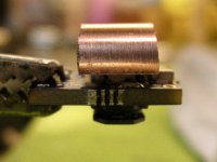
You can do that with some tapes which designed to transfer heat, but what I've done is find small copper pieces on ebay which are pre-cut or file them down to the size I need and glue it to the top of the chip which needs heatsinking, then the circuit board is raised enough the components don't touch. It irritates me the designers of these drivers have built them where that is necessary, in some cases. I believe all of those drivers should have a flat piece of copper already glued on top of the chip so we don't have to deal with it. Of course, there will be increased cost for that.

7) Has anyone experienced the driver 'popping off' from its location where it was bonded, after the thermal epoxy cured ?

YES, file down the excess glue, clean with solvent, try again. It is a good to first file the top of the chip to roughen up the surface before mounting with glue, this will help it stick better.

8) What about thermal pads, clay, putty? Are they all the same thing? Has anyone experienced a blob of clay debonding and rattling around inside the host?

Never had that, I don't like using thermal pads as they usually have more resistance to heat than simple heatsink compound or epoxy glue[i/]

9) Is it better to have a driver heatsink which is separate from the diode heatsink so both are not contributing heat to the same heatsink?

Yes, better, especially for high power laser diodes which produce more heat from the diode itself, as well as the driver too.

10) How much of the total heat is generated at the driver vs. the diode?

All of the drivers I use or have seen for sale are by far more efficient than the most eff. diode, likely all CC current units are unless an improper design. What this means is the diode will produce far more waste heat than a common laser pointer driver.


I have a high current 50 amp FAP800 driver which is spec’d at 95% efficiency, many drivers have eff. at 90 and higher percent, depending upon design, check the specs to see, some don’t do well but they are also cheap, not a big deal to me as long as the diode is not damaged, but longer lasting batteries for pointers and or less heat for CNC is good to have.

11) What is the best way to attach a driver to the inner surface of the battery tube of the host (since the board is flat and the tube is curved)?

You can either make, or buy half-moon inserts to match the curvature of your tube.

12) Generally, which comes first: attaching the leads to the driver or attaching the driver to the heatsink (for convenience and ease of
assembly) ?

Attaching the wires to the driver first, then the driver to the heatsink.

----------------------------------------------------------------------------------------------------------------------


One, two or three questions would probably be answered much quicker. That said, in my opinion most members just don't want to spend the time to answer that much. I can, I do that a lot because I have nothing better to do, it seems, but I just didn't see your post earlier, I don't go into some sections often, if at all.
 
Last edited:

Giannis_TDM

Well-known member
Joined
Apr 27, 2019
Messages
895
Points
93
The diode produces far more heat than most drivers. Many drivers are very efficient, 95 percent or higher, unless a homemade driver using something like a LM317, then they can get very hot too
Sadly I have to disagree on that, Most drivers I have tested from X wosse tung and flaming pyro range between the mid-80s and the best around high 80s low 90s. 95% efficiency is _very hard_ to get. Even my drivers only hover around the 92-94% mark and in special cases go up to 97(really high vf loads with a close input voltage like the laser bank I recently featured in my drivers thread) In the worst cases I have seen some x wosse drivers being really inefficient when boosting like my 525 1w build, there the x wosse driver was constantly overheating and turning the laser off. You can also optimize your driver for either low currents or mid high by changing the inductor for one with more/less inductence and more Isatalso the benefit of having a lower resistance, the output capacitors play a big role too. Higher quality caps typically have less ESR which helps a lot together with putting more caps in parallel. My drivers (except the 400mA boost ofc) are optimized for mid to high output currents.
 
Last edited:
Joined
Jan 29, 2014
Messages
12,031
Points
113
Diachi? Regardless of which driver is more or less efficient, here's an answer which more directly answers him:

10) How much of the total heat is generated at the driver vs. the diode?

All of the drivers I use or have seen for sale are by far more efficient than the most eff. diode, likely all CC current units are unless an improper design. What this means is the diode will produce far more waste heat than a common laser pointer driver.

I have a high current 50 amp FAP800 driver which is spec’d at 95% efficiency, many drivers have eff. at 90 and higher percent, depending upon design, check the specs to see, some don’t do well but they are also cheap, not a big deal to me as long as the diode is not damaged, but longer lasting batteries for pointers and or less heat for CNC is good to have.

Expensive and not for the power levels you are likely using. see: 97% https://lenlasers.com/catalog/power_supplies_and_drivers/laser-diode-driver-sf6040/

The BlackBuck8 driver has a specification of 93% efficiency on one web site I went to, but I believe there are two versions. I've tried to find the efficiency of the SXD driver, but not seeing it anywhere, that is probably due to having an efficiency which cannot be boasted about, one seller said "high efficiency" but didn't bother to specify what it was.

Edit: Good DTR LPF info, below

By the way, your questions, at least to me, show you must be fairly experienced with these things already.

.
 
Last edited:
Joined
Jan 7, 2012
Messages
149
Points
18
Alaskan, a BIG THANK YOU for taking the time and effort and patience to answer my questions!
Now I just need to take it all in and let all the info digest for some time.
Great information from your past experiences which clears up many questions I've had for a while.

For question #6, is the copper piece on top of the chip the heatsink itself or is it meant to then be glued to the heatsink - like the board being glued to the heatsink upside down?
 
Last edited:
Joined
Jan 29, 2014
Messages
12,031
Points
113
It probably doesn't matter if the copper spacer is glued to the chip, or to the heatsink, but placement of the larger heatsink is less cumbersome if the spacer is on the chip. It isn't as efficient as using one heat sink alone, but if the spacer is glued to the chip with epoxy, my guess is good enough, doing such was good for me with a 7 watt NUBM44 laser diode. If you are using this for CNC for long duty cycles, it would be better to have a single piece heat sink with either very aggressive air flow (lots) and a large heat sink, or for a smaller profile heatsink with a TEC or perhaps water cooling.

I don’t know if it makes a lot of difference, but my assumptin is to have maximum heat transfer you may want to consider using a single block of copper or aluminum machined with a footer to match the dimensions of the little chip on the driver. Probably better just buy a commercially made head myself if this is for CNC, unless just a hobby. www.optlasers.com sells a nice head.

Warning: If buying a CNC laser head on ebay, especially if from China, they specify the power for the INPUT to the head, not the OUTPUT of the laser diode, and even then inflate the figures further beyond the real output. Lies, lies, lies.
 
Last edited:
Joined
Jan 29, 2014
Messages
12,031
Points
113
Nice help Rich, I tried to find a half-moon copper or aluminum piece which can be used to mount a driver on the inside wall of a tube, but have been unable to find a photo of one. I believe you had offered those in the past, do you have a photo?

For a copper shim to glue to a driver chip, I've purchased these in the past and cut them to size:


Also, if the above are too thin, I have used these, but filed the fin side down flater. These alone do not offer much additional heat dissipation themselves, but work well as a material to fashion a shim out of, if you don't mind the extra work of filing those fins down flat. The fin side might also be good with epoxy to glue it to the larger heat sink, as the glue can hold it tight between the fins, but I would still file it down some to reduce the width of the gaps between each fin. May be moot though, these are so thick, you will probably want to file them down to a thinner thickness anyway:

 
Last edited:
Joined
Dec 15, 2014
Messages
6,782
Points
113
Nice help Rich, I tried to find a half-moon copper or aluminum piece which can be used to mount a driver on the inside wall of a tube, but have been unable to find a photo of one. I believe you had offered those in the past, do you have a photo?

For a copper shim to glue to a driver chip, I've purchased these in the past and cut them to size:


Also, if the above are too thin, I have used these, but filed the fin side down flater. These alone do not offer much additional heat dissipation themselves, but work well as a material to fashion a shim out of, if you don't mind the extra work of filing those fins down flat. The fin side might also be good with epoxy to glue it to the larger heat sink, as the glue can hold it tight between the fins, but I would still file it down some to reduce the width of the gaps between each fin. May be moot though, these are so thick, you will probably want to file them down to a thinner thickness anyway:

Hi
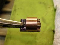
Ok here is the half diameter copper sink to fit inside the 12mm hollow back half
 
Joined
Apr 2, 2009
Messages
10,662
Points
113
lots of good replies by all.
I will add this:
just in case you do not know (I found this out the hard way)
While JB Weld is a great choice for many uses.. BUT because it contains iron===
never use it where you will be shorting out something if it touches the wrong places.

any body here that can find a driver and fix my 'F'-up with of huge DPSS 532 200mW module.??

Will take pics and post them here later--THANKS in advance,
I hope all it needs is a new driver correctly connected.
I got it from Laserlands when they had forum discount.
Never saw it FS anywhere since.

I did not know what I had done UNTIL later when I used JB Weld to glue a magnet to something.. I set it aside while the JBW 'cured'
When I looked later the JBW had moved from where I had it and 'crawled' on top the entire magnet --duh! and LOL at the same time.

peace
hak


Top