Thank you for keeping this post on a level of constructive criticism, it's greatly appreciated.
Your welcome! Agreed, and likewise appreciated. :yh:
I think you will find that the
overwhelming majority of ppl here at LPF are quite helpful & friendly. But like any group this large, there are a
very small minority of folks who unfortunately like to pick fights and instigate trouble. You can usually tell them, as they are the ones that engage in personal insults and other ad hominem attacks, rather than civil technical discourse.
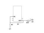
The only difference from the outlined design is that I have added a pot to the output pin (wiper and 2 to the output pin, while 3 feeds the pos. on the LD).
Based on your post #30, that is what I suspected might be going on.
The placement of resistors is
VERY important in regulator design. If you take a look at the first schematic of an example voltage regulator on the first page of the LM317T data sheet, and compare that to the design of the DDL current regulator, you will see what I am talking about!
While you have a constant-voltage source supplying it, what you have for
CURRENT limiting then is a
series resistor. Using a series resistor to control current is the same approach taken by this much-despised design -
Blu-Ray Laser Phaser!
or those cheap driverless Chinese red pointers that burn-out after a while.
While using an actual current regulator to drive a LD
is required, having a voltage-regulated power supply feeding into it
is not, and is usually done for fancy/high-end devices (like pro scanners, or labbys), or for AC line operated devices, where voltage surges, spikes, transients, etc. are a greater problem.
For battery-powered devices, the issue is a very small/short voltage spike that may sometimes occur when the power is first applied, and which can
easily be absorbed by a cap. A cap is, in fact, the
only form of voltage regulation in many laser driver designs, such as the DDL.
Having a voltage regulator that feeds into a current regulator is the top-of-the-line for a linear design, but likely overkill for most battery-operated handhelds.
Now, I expect you are chomping at the bit right about now to tell me something, and I
DO understand your position as expressed in your posts above, so let's jump right into the heart of the problem, shall we?...
At the OUT pin, correct.
by the feedback pin sensing resistance ( by two resistors) between FB and the out pin as well as FB and ground
Not exactly. R1 & R2 form a
voltage divider, which provides a portion of the output voltage (reduced to R2/(R1+R2) ) to pin FB (see pg. 9 of the data sheet, start of 2nd paragraph on right). The device adjusts the power to the output pin so that the voltage sensed at FB is equal to the internal reference voltage - this is how the device adjusts for errors/changes and keeps the voltage the same!
and not by sensing voltage drop or resistance across the LD.
Not across the LD - correct.
With the diode unable to interfere with those two isolated values the voltage value delivered will not change.
No, actually if a change in the load causes the voltage to start to change, the resulting shift in the single value (voltage at sense pin) will cause the device to correct (output more or less current), in order to maintain the desired voltage.
But you are correct that the LD cannot alter the
RATIO of R1 to R2, which is what sets the voltage.
With the voltage fixed...
Correct.
then I am able to limit current
Maximum current, yes. Actual current, no.
This is what controls the ma to the diode.
No.
If you were powering a static resistance load, then what you are saying there is correct.
But here is where it gets tricky.
A Laser Diode is
NOT a fixed resistance. It is an
active device, which consumes
a specific amount of voltage (forward voltage) that it wants to from the circuit
at that time, and which as brtaman rightly pointed-out, can
CHANGE based on circumstances (including the amount of current being drawn by the device, output power level, and temperature).
This is the reason that a "dummy load" for adjusting a laser driver has to have
active diodes on it, rather than just static resistors - to produce this same kind of "consuming voltage" effect!
") As a result of all of this, you cannot consider an device like a laser diode to be a simple resistor, for purposes of calculating Ohm's law.
As a result of all of this, you cannot consider an device like a laser diode to be a simple resistor, for purposes of calculating Ohm's law.
So what you have to do, then, is determine the amount of voltage drop across the
resistor, then apply Ohm's law to
THAT in order to calculate the current! As the current for loads wired in series is the same, this will also be the current being consumed at that time by the laser diode!
 This is, in fact, how you measure current on a dummy load - by measuring the voltage across the resistor!
Unfortunately, you
cannot calculate all of this ahead of time. Here's the problem -
Because the voltage across your pot is going to be what's left-over between the total voltage and what the LD is consuming (because they are in series across your regulated 5.6V), when the forward voltage of the LD
changes, the voltage across the pot
will also change. As the pot's resistance does not adjust itself when this happens (because it's
not a current regulator, it's just a resistor!
), this change in voltage drop across the resistor
increases the current as well! 
That is why in laser driver designs like rkcstr and DDL, they attach a sensor lead
AFTER the resistor (between it and the diode), so that they can
sense this change, and
automatically correct for it!
Unfortunately, due to the multiple integrated devices and complex design of the chip that you were using (including the internal interactions when operating in low-noise boost mode as your application required), I was doubtful that it was even
possible to operate this particular device as a reliable LD driver. It sounds like Erdabyz was alluding to some of the same concerns, when he indicated -
big and with some functions not required for this kind of drivers, that also difficult the design.
You had also indicated that this chip was
pricey, and I also knew from my own recent research into regulator chips that there were other devices now available that were not only better suited to your application,
but also quite inexpensive! :yh:
Seoguy, check out the latest posts here Erdabyz's switching laser drivers
I noticed that after your last post - thanks! :yh: I am looking into his designs now - will likely have some hopefully interesting comments for him about that shortly!
BTW, I tried to take the time for you to write this post about a fairly complex topic in a manner that was hopefully understandable. Please let me know if you have any more questions about all of this!