built ddl circuit fried one, got help on second go around, Red Ld lasted thru 1 9v , discharged cap, replaced 9v and result is very little light. Maybe hooked up the lm317 to the digikey 100 ohm pot wrong. Maybe the 3.9 ohm resistor was the wrong choice for the driver. Don't know. Here is a pic of the bottom and top side of the digikey pot #3319P-101-ND. Can someone please tell me the proper way to hook these two items up . . And, should I be using 2- 10ohm 1/4 watt resistors in the driver instead of 1- 3.9 ohm . Thought I had built this properly. Sorry the picture is not that good. Thanks

Welcome to Laser Pointer Forums - discuss green laser pointers, blue laser pointers, and all types of lasers
How to Register on LPF | LPF Donations

Navigation
Install the app
How to install the app on iOS
Follow along with the video below to see how to install our site as a web app on your home screen.
Note: This feature may not be available in some browsers.
More options
You are using an out of date browser. It may not display this or other websites correctly.
You should upgrade or use an alternative browser.
You should upgrade or use an alternative browser.
fried another red
- Thread starter madleds
- Start date


- Joined
- Oct 26, 2007
- Messages
- 5,438
- Points
- 83
Get a multimeter and measure it. If you don't have a multimeter, that's probably a good reason why you've fried your diode.
- Joined
- Feb 23, 2008
- Messages
- 2,832
- Points
- 48
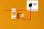
there really is no wrong way to hook up a pot as long as 2 of the pins are connected. which pins you connect will detemine if it will adjust clockwise or counter clockwise. the pic below is the setup for the pots i use. just make sure your hooking up the adj pin to one of the other pins. doesnt matter which pin b/c it will determine which direction you have to turn to go up or down...
p.s. the badger brings up a good point...how are you testing the current for the driver?
p.s. the badger brings up a good point...how are you testing the current for the driver?
Attachments

rog8811
0
- Joined
- Jul 24, 2007
- Messages
- 2,749
- Points
- 0
Here you go...
This is a recently bought SenKat red I assume... (goes off to read thread again :") ) 3.9 ohms should have been ok, as long as this pot is 100ohms it should be ok as well, measure it to make sure..... although any value would be fine, it would just be more difficult to adjust.
) 3.9 ohms should have been ok, as long as this pot is 100ohms it should be ok as well, measure it to make sure..... although any value would be fine, it would just be more difficult to adjust.
Regards rog8811
This is a recently bought SenKat red I assume... (goes off to read thread again :
) 3.9 ohms should have been ok, as long as this pot is 100ohms it should be ok as well, measure it to make sure..... although any value would be fine, it would just be more difficult to adjust.Regards rog8811
Attachments
I am hooked up the opposite of what this shows. I have the out on the 317 going to the pot with the the two pins that are connected together. Opposite of what you have done rog. Make a difference huh! I did all the testing with the dummy load as you helped me in the past couple weeks. The numbers were good but when I hooked up the Ld, There was not enough light coming out to do any thing. So I turned up more until it burned. Check the #'s and they were very high. Turn it down to qt turn and hardly anything. I will try and remake circuit in a bit using my new breadboard. Anything eals you could think of would be great. As always ROG thank you and you to DREW. I'll let you know how it turns out. Mike
rog8811
0
- Joined
- Jul 24, 2007
- Messages
- 2,749
- Points
- 0
Makes no difference at all....I am hooked up the opposite of what this shows. I have the out on the 317 going to the pot with the the two pins that are connected together. Opposite of what you have done rog. Make a difference huh
remake circuit in a bit using my new breadboard
Try soldering it together, I rarely use my breadboard for power supplies as contacts can be disturbed so easily..
Regards rog8811
rog8811
0
- Joined
- Jul 24, 2007
- Messages
- 2,749
- Points
- 0
Thanks, I am not exactly over run with members
daguin
0
- Joined
- Mar 29, 2008
- Messages
- 15,989
- Points
- 113
rog8811 said:Thanks, I am not exactly over run with members
EVERYONE -- GO LOOKY HERE
http://rog8811.webs.com/
Toot your horn, Man!
Peace,
dave
rog8811
0
- Joined
- Jul 24, 2007
- Messages
- 2,749
- Points
- 0
Thank you dave, do you think anyone will notice?Regards rog8811