Kizdawg
0
- Joined
- Feb 7, 2012
- Messages
- 977
- Points
- 0
OK Then your ahead of me... the round ones are a breeze.. I love that format..
Last edited:


Follow along with the video below to see how to install our site as a web app on your home screen.
Note: This feature may not be available in some browsers.


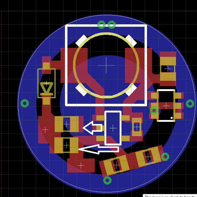

I tested it on a testload and got a solid reading of what I was expecting. Is the driver safe to use? The caps are bridged.
 ... if so that is a serious mistake that will lead to no current regulation. like draw a line what needs to be bridged
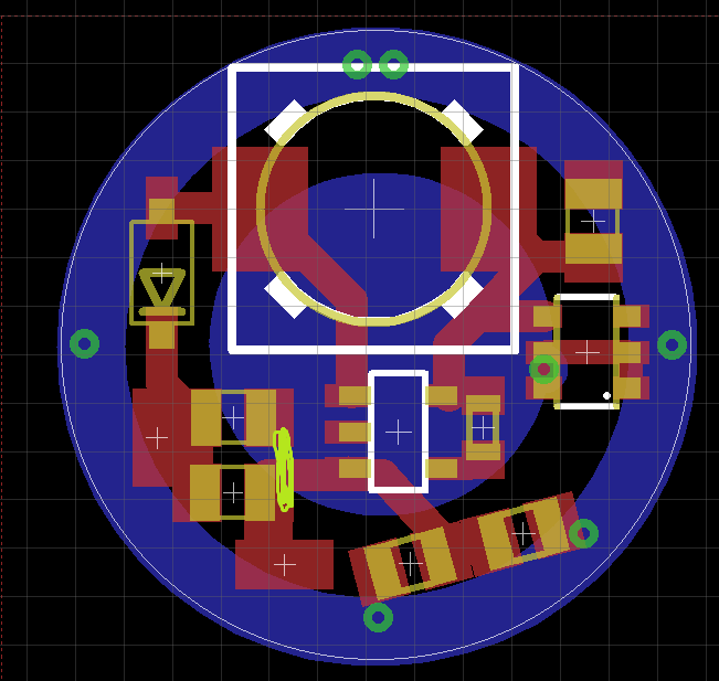
Foulmist... I have no clue what you just said. I don't know anything about this. I tested it on a test load though and got a constant output, and now put it into a build and shes working.
well I am not sure what you did there. But if you are using the layout with bridge there is no output cap which is bad. ")
Hmm odd... I got the Digikey order today Man there fast! I put a board together with a 1.6ohm resistor on r1 and I am getting about 172ma out with a 14500 and 191ma with a 18650... the math say's I should be getting arround 118ma...