skir0987
0
- Joined
- Nov 26, 2011
- Messages
- 86
- Points
- 8
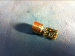
So I have no killed two diodes the exact same way, and I can't figure out what is going wrong. I have a micro flexdrive from cajunlasers, an LPC-826 from cajunlasers, a Mastech power supply, and a home-built test load. Here is my procedure:
1. Hook diode in aixiz module up to power supply, feed it 400mA with. All good.
2. Connect four diodes (1N4004s from radioshack) up on my test load, connect my + and ground up to the flexdrive, put multimeter test leads up to resistor (1-ohm 10-watt from radioshack), run 4.0V through flexdrive. Reads 395mA, power supply is saying it's putting out 0.38A, so just about the same. All good.
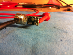
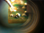
3. Short + and - to diode out on flexdrive, solder laser diode pins to proper places on flexdrive, hook flexdrive up to power supply (which I have not touched since testing with the test load, and turn on. Laser flashes bright for a fraction of a second them dims down to almost nothing, I can see a point with a line through it, so I assume it is LED'd. Power supply says it's putting out 0.49A. :wtf:
4. Hook diode directly back up to power supply, feed it 400mA, and I get the same dim dot with a line through it.
I do all of this with a grounding wrist strap on. I've gone through this exact procedure twice now with the exact same result. I have one more diode to test this on before I give up altogether. Can anyone help me figure out what's going on?
Here's a diagram of my test load circuit:
+ in----1N4004----1N4004----1N4004----1N4004----1ohm, 10watt resistor---- gnd out
The positive current is fed through the side of the 1N4004's with no band and out through the side with the silver band.
It's based off the diagram in this thread: http://laserpointerforums.com/f51/how-make-selectable-dummy-load-very-depth-64585.html
Thanks,
Shep
Last edited:


