Welcome to Laser Pointer Forums - discuss green laser pointers, blue laser pointers, and all types of lasers

Buy Site Supporter Role (remove some ads) | LPF Donations

Links below open in new window

FrozenGate by Avery

First scanner advice needed, right step into scanners?

Ah haaaa kerching. Penny just dropped! lol


One more thing that confuzzles me.. The manual for my analog lasers modulation wires are labelled + and - yet that is marked as negative but goes to ground? If something is marked negative in AC, as you stated, the last thing you want to do is connect it to ground.

The signal is a waveform, yes but it is all positive, so it is a DC signal.

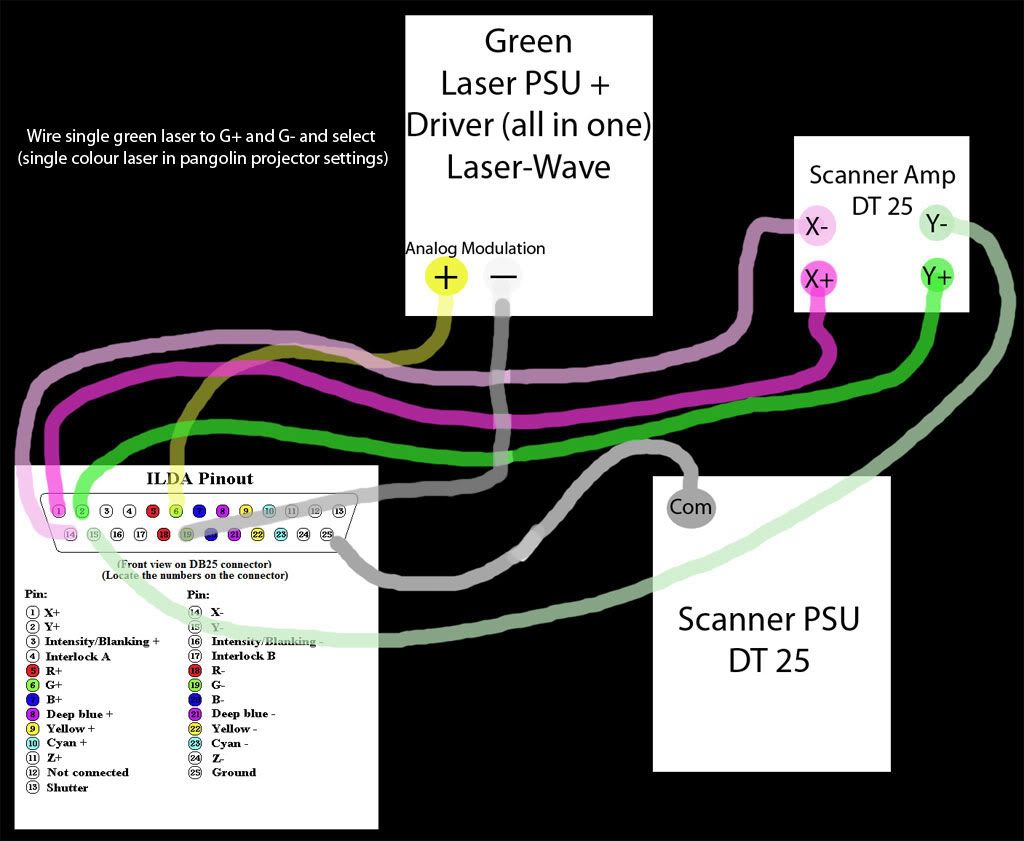
Regarding that diagram, the gray wire is the yellow wire on your module. The other wire isn't pictured in that diagram, but it goes either to ground or the I- terminal.

As for the G or I channels, I is meant for single color scanners, but not all DACs support it. I believe the FB3 does, so that's what you should use.
The intensity channel works just the way you described.. I think you're starting to get this stuff!
 
Last edited:


Ah haaaa getting there :D So with me having an FB3 i need to know if i should use the intensity channel or not.

I think after i find out this last detail i can go ahead and build my scanner with confidence that i know what i'm doing.

Thanks for the help, it really is highly appreciated
 
Never a problem.. glad to help! Just make sure you post pics when it's done..

It was mentioned in another thread, but not here and it's quite helpful so I'll talk about it here too:

When you first go to set everything up, go buy a thin 5-7mm sheet of plywood and cut it to exactly the same dimensions as your mounting block.

Mount, power up and align everything on this sheet of plywood. When you have everything aligned properly, take everything back off the plywood and use it as a drilling template for the aluminum plate. This will eliminate any issues you may run into with the beam exiting the laser at an angle rather than perfectly straight. This happens very often with DPSS lasers.

This technique is very helpful when building a single-color system and indispensable when building multi-color..
 
Last edited:
Spot on :D great tip!

Just had it confirmed, for an FB3 the modulation wiring on my single green laser goes simply to +G and -G then in the projector software i select 'Single colour laser and everything will be output to the green channel :D

My chunk of aluminium arrived this morning. :D

Pics will come as i build.

Connections-to-ILDA-1.jpg
 
Last edited:
I would recommend setting it all up on your alu plate first instead of plywood, since some things may have case voltages and blow stuff up, better to blow things up before you mount it all down :)
 
I would hope that that laser-wave module would have the case isolated.. but I don't know for sure on that one. Never had any problem with CNIs being case-positive, and since laser-wave split from CNI I would assume some of the manufacturing techniques would carry over. An obvious solution would be to isolate the aluminum block and use the scanner's case as ground instead.

I am curious why you would post something that vague ("since some things may have case voltages and blow stuff up") and then not elaborate? Not interested in possibly helping someone save their equipment? I guess that must be too close to spoon-feeding for you..
 
Last edited:
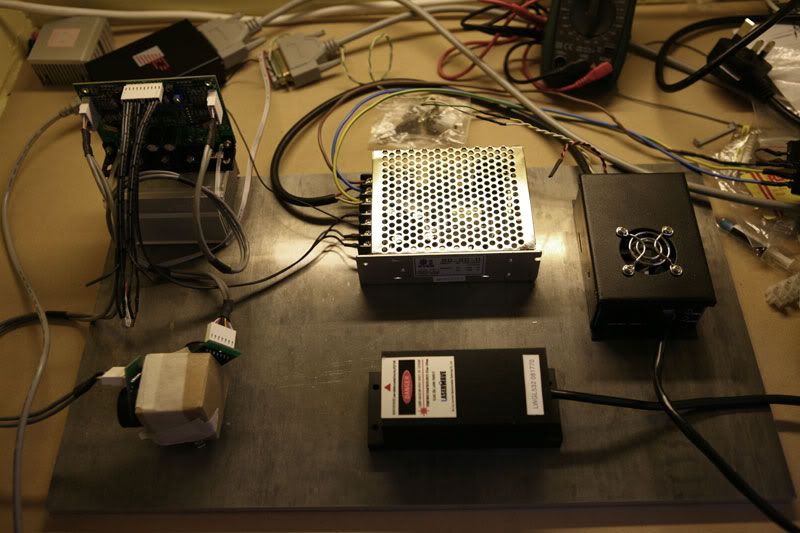
Well this is my gear, it is only layed out like this for testing, everything works spot on :) This 470mm X 270mm 10mm plate will be installed just below halfway down the case.

I decided to make my case out of wood. I think i've made the right choice as its going to be used at home or maybe sometimes partys so asthetically i wanted it to look like a moderm piece of furniture, I think it'll look nice this colour. I used 18mm ply with a decent grain, this is rock solid strong as is, my next job is to install aluminium angle on the outside edges for added strengh and to hide the ply stripes, i'll also polish up the aluminium edges. The wood will be just waxed probably.
opticalplate.jpg


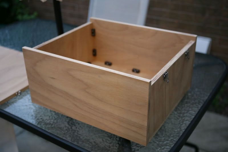
Case opened, the lid fits perfectly and i have something in mind to keep out dust. I have a pretty good cooling idea up my sleeve ;)
caseopen.jpg


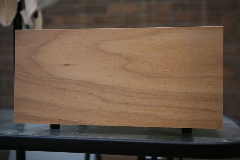
This is the front, I have yet to cut the square hole for the laser but this will come after i've installed everything on the optical table. I just used Door stops for the 4 legs, they work perfect :D
casefront.jpg


Lid back on. clips on the side are handy. they hold the lid on solid and its nice & quick to remove.
case.jpg


Wood £23
Alu plate £40
fans will be about £40 for the 2. I'm using these: Noctua NF-P12 Vortex-Control 120mm Quiet Case Fan

It'll be a few quid for the aluminium angle to finish off

Jobs left to do:

Install back plate for ILDA interface, Power, key lock.
Install 120mm fans and filters ;) i have some very quiet ones lined up in brown.
Clean up the optical plate.
Install components to optical plate. I am setting this up for RGB. The optical plate will also be installed into the case so its quick to remove.
Align optics, mark out maximum exit aperture, remove the optical plate and cut out the square exit hole, install glass (still not sure, i'm sure you can get square camera filters)
 
Last edited:
^lookin' GREAT! I especially like the case.

If you're setting it up for RGB, have a look at this pic:

477-rgb-scanner-interior-30k-galvos-all-cni-modules-50mw-473nm-100mw-532nm-300mw-650nm-pic-yobresal.jpg


The green laser is the farthest to the right (horizontal) and the red and blue are next in that order proceeding to the left(both vertical). This is the kind of configuration you'll have when you build your RGB. You'll want to mount the green laser far enough over that you still have room for the blue and red. Depending on the power of your green, you'll need a very powerful red laser and a relatively powerful blue laser for a decent white balance. Green lasers tend to swamp out all other colors since the human eye is most sensitive to green. Powerful blue lasers tend to be quite large so keep that in mind as well. You can see that the blue is the largest laser in my RGB.
 
Last edited:
I've just epoxied a 10mm X 10mm mirror to a mount as i'll be running the green vertical to give more spacing and room to the other 2 lasers. I've had a chat with Rob at Laser wave about a red. I think i'm gonna order one from him as soon as i decide which red to go for.

What is the width of that optical plate? I'm mounting all of the PSU's either on the back of the casing or under the optical plate.
 
^regarding red, go with the new 640nm. Absolutely badass beam specs for a diode and better visibility.. they do cost a bit though.

Regarding the size of the plate, I'm not sure exactly and I can't peel the cover off for a look ATM.. I'll take a quick measurement next time I have it open. I didn't build the scanner as you can tell by the cheap dichro mounts, it was made by a Chinese company called LKI. Most of the time I'm a little leery of Chinese scanners, but this one uses all CNI lasers and they're all overspec. The craftsmanship on the inside is decent as well.. the ideal way to build a scanner for long-term optical cleanliness is to place the PSUs and fans under the plate, but have the plate be the bottom of a sealed upper compartment for the laser heads and galvos. Any fans up here should be avoided unless you're working with very high-powered stuff. If you feel you need fans on the upper level, filters are obviously an absolute must.

I don't practice what I preach in this regard since all of my systems are one single level in a box. The only disadvantage is that I have to get inside and clean all the optics once in awhile, but I like checking in on things from time to time anyway..

Also, about your configuration. There is nothing wrong with turning the green beam with a mirror like you said, but remember that every optical item (mirrors, lenses, dichros, etc) cost you power. Less is more in this case.

Did Bill ever help you with your "smokey" fb3 issue?
 
Last edited:
^regarding red, go with the new 640nm. Absolutely badass beam specs for a diode and better visibility.. they do cost a bit though.

Regarding the size of the plate, I'm not sure exactly and I can't peel the cover off for a look ATM.. I'll take a quick measurement next time I have it open. I didn't build the scanner as you can tell by the cheap dichro mounts, it was made by a Chinese company called LKI. Most of the time I'm a little leery of Chinese scanners, but this one uses all CNI lasers and they're all overspec. The craftsmanship on the inside is decent as well.. the ideal way to build a scanner for long-term optical cleanliness is to place the PSUs and fans under the plate, but have the plate be the bottom of a sealed upper compartment for the laser heads and galvos. Any fans up here should be avoided unless you're working with very high-powered stuff. If you feel you need fans on the upper level, filters are obviously an absolute must.

I don't practice what I preach in this regard since all of my systems are one single level in a box. The only disadvantage is that I have to get inside and clean all the optics once in awhile, but I like checking in on things from time to time anyway..

Also, about your configuration. There is nothing wrong with turning the green beam with a mirror like you said, but remember that every optical item (mirrors, lenses, dichros, etc) cost you power. Less is more in this case.

Did Bill ever help you with your "smokey" fb3 issue?

Yeah, ultimately i'll have the upper level with the optics and lasers sealed, i have installed the power supplys to the bottom of the plate too.

I'm looking into getting a 640 red off rob, i should have that next week, i may aswel go for RGY for now then have a think about the blue or violet. a little later.

I test ran my green in the garden last night. This was my first experience of seeing what my gear can do with the Pangolin FB3.. Man, as i've said on PL i nearly cried with joy! Its out of this world. Yesterday i bought a nice Antari 284 m3/min smoke machine ready for the first test...... The experience was Incredible, i could hear the neigbours saying WOWWW!! etc. I walked to the end of my garden and looked back up & down the steet, nearly everyone was looking out of the window watching lol. Anyways, 2 hours of ambient themed awesomeness and this was only a test, the red is to come then it'll all be installed in the housing and accurately aligned.

Bill has me sorted regarding the FB3, to be honest i wasn't really all that fussed anyway, the minor things had no bearing on the sheer power of the FB3 and i only mentioned them in that thread on PL just to point out i had pretty much the same cigar smell etc, really though, i wished i hadnt mentioned it as it really is nothing. Last thing i'd ever want to do is tarnish the brilliant reputation of Pangolin.
 
LOL.. You've been bitten. The symptoms are long-lasting and will never fully go away. Your wallet won't forgive you and there's a good likelyhood your spouse (if any) won't either. But it's LOTS of fun. For the neighbors too!!!
 
The way i see it... Its only money, i could pop my clogs tomorrow having not experienced certain things that cost money. I'm happy to seperate with this kind of money to gain this amount of pleasure :D
 
Hi there. Again help needed :yabbem: I made the audio dac mod, the laserboy correction amp and its calibration and connected to XY galvos. All worked, i can see the ILDA test pattern but without TTL is shows choppy. Well So I connected the TTL cable to correction amp, and... WTF I see the same image than before for the ILDA test without TTL but, HALF SCREEN !! :thinking: if I invert the polarity of the TTL connection I see the other half screen. I am stumbled upon this, can't imagine what to test. The same thing goes on with several TTL lasers that I have. What have I done wrong? What a pity! I was so happy... Anyone can suggest any test, or has anyone had the same problem?

Thanks in advance for your time.
 
Post some pics if possible. I haven't experienced that issues, but detailed pics of the output before and after connecting the TTL cable, along with detailed pics of your DAC setup might help me determine possible causes.


Back
Top