XysteR
0
- Joined
- Apr 26, 2009
- Messages
- 49
- Points
- 0
I know I'm not Things, but that would be m-4 metric..
Ah do you have the DT25's too?

Follow along with the video below to see how to install our site as a web app on your home screen.
Note: This feature may not be available in some browsers.

I know I'm not Things, but that would be m-4 metric..


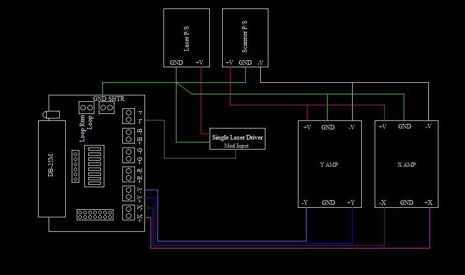
Hey guys, just wanted to try and help clear something up a bit. On XYsteR's amp, the pin has the "sideways T" label really should be left disconnected all together. ILDA pin 25 (GND or Ground) should be attached directly to the scanner power supply, in particular to the screw labelled "COM". This will prevent a ground loop.
The wiring for the laser can also be a bit wierd. Ideally, you would only connect "modulation +" line and leave the other disconnected, and attach ILDA pin 25 to the 0V rail of the laser power supply. A laser that has the driver and power supply built together, or if the modulation input is isolated for protection (seems the Laserwave lasers have this built in) will need to have both "modulation + and modulation -" attached. However, the "modulation -" should be attached to ilda pin 25. The R-, G- and B- are really for a laser that has a differential front end, which most of them do not. Some DAC's can handle having these lines (R-, G-, B-) grounded, then you can use them if you have to. If your DAC is able to handle having the minus lines grounded, and you have a breakout board, then you can just turn on switches 3, 4 and 5 to ground the minus lines on the breakout board.
Yes M3 or M4.
I wont be here to reply for a few days, I am down picking up a few laser goodies from Dave @ LSP
I wont be here to reply for a few days, I am down picking up a few laser goodies from Dave @ LSP
Perfect! That's precisely right. I like the diagram.. never seen it drawn out quite so simply, which makes it very easy to understand.
that's how it's done..


