Welcome to Laser Pointer Forums - discuss green laser pointers, blue laser pointers, and all types of lasers

LPF Donation via Stripe | LPF Donation - Other Methods

Links below open in new window

ArcticMyst Security by Avery

First power supply

Joined
Dec 17, 2012
Messages
2,081
Points
63
If I were go build something likw this I would need a diagram with part numbers and what not haha


Joined
Dec 11, 2011
Messages
4,364
Points
83
Yeah I had thought about the passbank idea but figured the price and build complexity would be too much for the non electronically inclined. I too saw the 317's dead cheap somewhere and was basing it on that.

The passbank does make current adjustment easier though. You still need to ensure proper current sharing though, which isn't as straight forward as a 317 bank since 317s will self regulate for temperature variances but the transistors will have different Vbe drops if their junction temperatures vary.
 

IsaacT

0
Joined
Aug 25, 2010
Messages
5,947
Points
83
I am looking at this;

HQ Power PS1503SB
Input: 115VAC 60Hz
Output: 0-3AMP

Do you think this would be good for diodes? Also price is 85 without tax...ripoff or no?
 
Joined
Dec 11, 2011
Messages
4,364
Points
83
Last edited:
Joined
Feb 10, 2013
Messages
2,125
Points
63
WB, before you buy...

I got mine from the post this morning before work. Here's a quick pick after unboxing.
sG0V50i.jpg


It's nice enough, and heavy. The fan in this one is not as loud as I've heard about in reviews. Maybe they fixed that.

I used it this afternoon to fire up an Osram 450nm and an S06J 405nm. Both lased and burnt beautifully!

Here's a link: ATTEN Vaiable DC Powersupply

Oh, if only I had an LPM!

So, is there a way to create a circuit or something that makes it usable on switching drivers? Hell, that was half my reason for justifying one of these!
 
Joined
Dec 11, 2011
Messages
4,364
Points
83
What do you mean "makes it useable on switching drivers"?

Do you mean use it to power switchmode drivers? Like Buck, Buck Boost, and Boost drivers? Just dial in the range of voltages and approximate currents the drivers are designed for and hook it up.
 
Joined
Feb 10, 2013
Messages
2,125
Points
63
I was hoping to use it for powering and adjusting buck and boost drivers. From what I've gathered, there just is no way to easily use this kind of PSU on a switching driver.
 
Joined
Dec 11, 2011
Messages
4,364
Points
83
Nonsense.

Set the psu voltage to whatever you're expecting the driver to run on nominally, add your dummy load to the driver, and set the PSU's current high enough to have plenty of overhead over the estimated maximum current draw.

For example if you have a boost driver intended for a single Li-Ion cell that is designed for say 405nm diodes at a maximum of 1A you do the following:

Assume a worst case Vf of 8.5V for the diode at a maximum If of 1A. Now that is 8.5W of power drawn from the driver, assume a worst case efficiency of 60% and multiply the 8.5W by 1.4. That gives you 11.9W of power. Now your single Li-Ion cell will nominally output 4.22V, but lets pick a central voltage range figure of 3.9V. 11.9 / 3.9 = 3.05A draw. Set your PSU to 3.9V @ >3.05A (let's say 4A), this will mimmic a fully charged Li-Ion cell with high internal resistance (or a half-charged cell with low internal resistance) under very heavy load. Now adjust your Boost (or Buck Boost) driver accordingly to get proper readings on the test load.
 
Last edited:
Joined
Feb 10, 2013
Messages
2,125
Points
63
Sig, thank you for your concise and abrupt response. I have not been able to glean this information so far. My own education in electronic circuits is still developing. I appreciate the very thorough explanation, and the solution to my problem. +1 for sure!
 
Joined
Dec 11, 2011
Messages
4,364
Points
83
Glad to help!

I'm still learning as well, well... any good engineer should be continually learning, truth be told. Anyway, I've just got a few years under my belt more than you do, that is all. Keep at it and it will all become clear. Electronics is one of those fields that make absolutely no F**king sense at all until you're up to your ears in it, and then suddenly you start to see things you missed before.
 
Joined
Sep 12, 2007
Messages
9,399
Points
113
sigurthr, there is a problem you will eventually run into with resonances and oscillations if you drive switching drivers with bench power supplies. The response time of the supply is often much slower than the switching frequency of the driver, and if the filter capacitance between the two isn't high enough, it will cause problems. Symptoms range from audible squealing, to lower-than-expected supply voltage, to premature current limiting, to physical damage.

"Why don't they just add more capacitance?" I hear you ask. Well, for drivers it adds cost and it doesn't matter because they're designed to be powered by batteries which don't care. For the power supply, adding more capacitance tends to stabilize constant voltage mode, but destabilizes constant current mode. So they'll usually pick something in the middle.

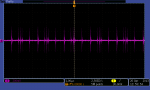
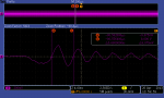
For the scumbag's original question, add a LARGE capacitor on your driver's input if you run into problems (And you might not - it really depends on what you're driving). This will smooth out the current pulses drawn by the diver and give the supply more time to respond, ultimately stabilizing the circuit. Do NOT use a capacitor if you expect to be running in constant current mode. Why? Because the supply only has control over how much current goes out. It is entirely possible that current out of the supply remains at a constant 1A, but has wild fluctuations at the end load because the capacitor is resonating with some other component.
 
Last edited:
Joined
Dec 11, 2011
Messages
4,364
Points
83
You're absolutely right, but I don't think it is a common issue for the kinds of loads one usually encounters. If the load's input impedance is too close to the supply's output impedance and there is too much coupling between the load and the supply you can get erratic current waveforms. Adding capacitance slows the CC supply's response time to dynamic loads because the dv/dt is limited by the RC value. Rapid di/dt should be seen by the supply unless the impedances are mismatched or the capacitance is far too low.

In my experience there is only one situation in which it is encountered; where you are powering a CC supply under test with a CC supply to check performance in an undercurrent situation. Outside of an undercurrent test high enough current overhead and large enough decoupling cap should prevent stability issues as long as the main supply is low enough output impedance in relation to the load's input impedance. In other words you have to fill the cap faster than you drain it.

I've only seen resonances pop up when dealing with purely inductive loads of extremely low impedance. I'm not saying that is only when it will happen, but my supply has enough and fast enough active regulation that unless the LC formed is of super high Q, the stability is solid. A dampening resistor makes a huge difference in these cases.

I didn't want to overload SBA (calling him scumbag is odd lol) with complex EE things he may not need to worry over. I tested out several laser drivers with no issue on a supply like his, hopefully he will have good luck too. I was probably misleading with my cry of "nonsense!", but I meant for it to be reassuring and helpful.

What do you suggest for a highly dynamic load with an impedance close to that of the supply where additional capacitance only worsens the stability?
 

phenol

0
Joined
Oct 30, 2007
Messages
533
Points
18
Don't neglect one of the basic 'properties' of modern switching laser drivers /and other power sources, for that matter/ - switching frequencies well in the MHz range and rise/fall times 20-10ns or even less. A poorly HF decoupled or shielded driver may deliver or radiate common mode HF noise thru the wires leading to the power supply, which propagates with ease around and thru the poorly performing at high frequencies electrolytic caps at the output to the sensitive feedback loops inside the power supply. What happens next is beyond imagination.
Even if you place large amounts of capacitance at the output, poor layout, bouncing grounds, etc may render it useless against HF noise. properly sized HF filter chokes in series with power leads may prove useful in defeating instabilities.
 

Things

0
Joined
May 1, 2007
Messages
7,517
Points
0
I find it unlikely that our laser drivers will be running even close to Mhz, probably a few hundred Khz at best.
 

phenol

0
Joined
Oct 30, 2007
Messages
533
Points
18
I find it unlikely that our laser drivers will be running even close to Mhz, probably a few hundred Khz at best.

even so, switching transients have very broad spectrum, up to VHF.

The once popular here LM3410 switches at 1.6MHz. I'm not sure about the abundance of TI chips on the forum, but they are definitely running upwards of 100s of kHz.

EDIT: Those screenshots were taken with a small 6-7cm loop pickup antenna around an LM3410 sepic driver running at 700mA on a PCB copied from the datasheet. As you can see, the ringing is close to 200MHz and amplitude is fairly large. One such thing would miserably fail any EMC test.
 

Attachments

  • tek00003.png
    tek00003.png
    15.5 KB · Views: 77
  • tek00004.png
    tek00004.png
    21.6 KB · Views: 94
Last edited:
Joined
Dec 11, 2011
Messages
4,364
Points
83
If they're really that high in frequency it is possible I'm just not able to see it then. I only have a 40MHz scope, and I know from my own tests that I can just barely see a 100MHz signal with a basic pick up loop. The attenuation of my scope probes combined with the lack of bandwidth of my scope would just make anything on the order of magnitude of a radiative signal absolutely invisible if it is in the tens to hundreds of MHz range. I'm good to about 4MHz maximum for actual useability, that's it. I can detect the presence of up to about 150MHz if conditions are optimal and I'm not blasting the input with a strong signal, just a normal logic level signal.

Now I've worked with RF circuits before a fair amount and have experienced RF runaway as I like to call it where routing, leakage, unwanted coupling, etc all come in to play, but I've never seen any laser equipment come close to any of that. Clearly there has been some thanks to the chip you linked, I'm just saying that I've never seen any myself. Small sample size is small - but it makes me wonder how many drivers out there are actually EMC failures.


Top