
Welcome to Laser Pointer Forums - discuss green laser pointers, blue laser pointers, and all types of lasers
How to Register on LPF | LPF Donations

Navigation
Install the app
How to install the app on iOS
Follow along with the video below to see how to install our site as a web app on your home screen.
Note: This feature may not be available in some browsers.
More options
You are using an out of date browser. It may not display this or other websites correctly.
You should upgrade or use an alternative browser.
You should upgrade or use an alternative browser.
Fade on / Current spike limitation
- Thread starter laytor
- Start date


Immo1282
0
- Joined
- Sep 4, 2018
- Messages
- 562
- Points
- 63
Not sure what thread you'd be referring to since that was ages ago - but usually people round here measure current with a shunt and a voltmeter. Something like a big wirewound 1ohm resistor makes it easy, so 1A=1VCyparagon
What did you used to measure the current on your 2013 post ?
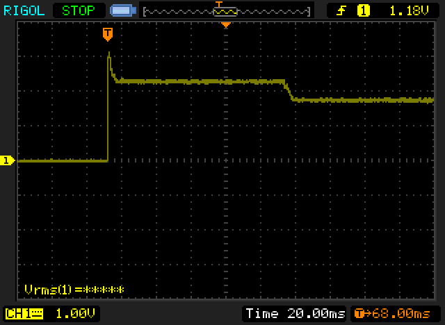
He posted this , but i want to know how he got this , i know that its an oscilloscope but its a current clamp plugged in or else ?Startup spikes are downright terrifying. And it would probably be worse (to the point of blowing up my test load perhaps??) If the voltage set point was higher. As always, note the time base in each image because they change to show detail.
At 1.8A switched before the driver:
Last edited:
Not sure what thread you'd be referring to since that was ages ago - but usually people round here measure current with a shunt and a voltmeter. Something like a big wirewound 1ohm resistor makes it easy, so 1A=1V
Is that what you where talking about :

1ohm 100w resitor Here
Edit : I tested on a 12v led strip :
Normal way :

58ma
Resistor way (used a potentiometer set to 1ohm) :

54mv = 54ma
Hey , it works ,thx.
I will do this on my DSO138 oscilloscope (it only cost 15€
") , simple and its enough for me)
, simple and its enough for me)I know how i to use this function : Here
Thats all good ,thx Immo1282
There is still the question of "soft start" but for now ...
Now its just a question of time to recieve everything....

Last edited:
- Joined
- Sep 20, 2013
- Messages
- 20,284
- Points
- 113
I have some 1% 1 ohm resistors in power ratings from 5 watts up to 100 watts. It is important to get the most accurate resistors you can to measure current using a shunt resistor. It is easier to incorporate either a 1 ohm or a 0.1 ohm resistor in a dummy load to measure the current as you don't have to interrupt your circuit to put an ammeter in series with it. Also, you needn't worry about blowing a fuse in your ammeter if you select the lower range than the current passing through your circuit.
I have some 1% 1 ohm resistors in power ratings from 5 watts up to 100 watts. It is important to get the most accurate resistors you can to measure current using a shunt resistor. It is easier to incorporate either a 1 ohm or a 0.1 ohm resistor in a dummy load to measure the current as you don't have to interrupt your circuit to put an ammeter in series with it. Also, you needn't worry about blowing a fuse in your ammeter if you select the lower range than the current passing through your circuit.
If i have a 1ohm +-5% or 10% i will still be able to see the current spike (on the dso) if there is one , and i can check the current precisely via my multimeter?
- Joined
- Sep 20, 2013
- Messages
- 20,284
- Points
- 113
Yes, you should be able to see noise on your line if it exists, but you won't have an accurate measure of your current. In order to get that you need large, short connections between components in your dummy load and the most accurate resistors you can find.
I have found a 3w 0.1ohm 1% resistor .Yes, you should be able to see noise on your line if it exists, but you won't have an accurate measure of your current. In order to get that you need large, short connections between components in your dummy load and the most accurate resistors you can find.
Immo1282
0
- Joined
- Sep 4, 2018
- Messages
- 562
- Points
- 63
Should do nicely - Specially made shunts work even better - but that'll be perfectly accurate to see what you need here. There are extremely high-precision high-current shunts avaliable but it's total overkill for a laser.I have found a 3w 0.1ohm 1% resistor .
- Joined
- Sep 12, 2007
- Messages
- 9,399
- Points
- 113
"DSO138"... What an absolute cat turd you've unearthed. I thought you said money wasn't an issue. You need to spend 10-20 times that to get something decent.
The DSO138 is a toy. And I say that as a matter of fact, not as a disparagement.
Close, but a differential probe isn't necessary if your power supply is floating. Yours almost certainly will be, but you've surprised me several times before here, so we shall wait and see what ungodly setup emerges from this.
Not only will the resistance and readings wander all over town, it'll explode or begin smoking once you pass higher current though it. I promise.
Not if you can measure and apply a calibration constant. The temperature coefficient is a far more substantial specification when it comes to accuracy. 0.001% resistor is useless as a shunt if it has a tempco of 10,000ppm/C
Look no further than the 8 digit multimeter for an example. Is the internal voltage reference accurate? It may surprise you to know that, NO it is not. The accuracy is a result of the stability and the temperature coefficient. The discrepancy in voltage is an easy calibration constant away from perfection.
Besides, we're looking at the startup waveform. The waveform is not altered if the units are off by 5%.
...What? Please elaborate, because I suspect KCL is about to prove you wrong unless I'm misreading something or unless you retract something.
The DSO138 is a toy. And I say that as a matter of fact, not as a disparagement.
Close, but a differential probe isn't necessary if your power supply is floating. Yours almost certainly will be, but you've surprised me several times before here, so we shall wait and see what ungodly setup emerges from this.
Resistor way (used a potentiometer set to 1ohm)
Not only will the resistance and readings wander all over town, it'll explode or begin smoking once you pass higher current though it. I promise.
It is important to get the most accurate resistors you can to measure current using a shunt resistor.
Not if you can measure and apply a calibration constant. The temperature coefficient is a far more substantial specification when it comes to accuracy. 0.001% resistor is useless as a shunt if it has a tempco of 10,000ppm/C
Look no further than the 8 digit multimeter for an example. Is the internal voltage reference accurate? It may surprise you to know that, NO it is not. The accuracy is a result of the stability and the temperature coefficient. The discrepancy in voltage is an easy calibration constant away from perfection.
Besides, we're looking at the startup waveform. The waveform is not altered if the units are off by 5%.
In order to get [accuracy] you need large, short connections between components in your dummy load
...What? Please elaborate, because I suspect KCL is about to prove you wrong unless I'm misreading something or unless you retract something.
- Joined
- Sep 20, 2013
- Messages
- 20,284
- Points
- 113
I never said that these are the only considerations to get the best accuracy when setting up the current using a dummy load. I use 1% resistors that have no inherent inductance or capacitance. It is also important to know the temperature coefficient of a resistor if you expect it will change with current. And what I meant for large, short conduction paths was for currents exceeding 4 amps where small, long conduction paths can add resistance and inductance to your circuit. Of course you are limited by the other components in your dummy load as to the accuracy you can expect, but if a 1% resistor like I've described is not much more expensive than a 5% one, there is no reason not to include it.
Last edited:
- Joined
- Sep 12, 2007
- Messages
- 9,399
- Points
- 113
for currents exceeding 4 amps where small, long conduction paths can add resistance and inductance to your circuit.
It's not only for long conductive paths, it's not just above 4 amperes, and it's not just resistance and inductance either. ALL leads have ALL parasitics (in varying quantities) at ALL currents. It's a law of physics. How exactly are you insisting these affect the accuracy of the current reading at the shunt?
Last edited:
- Joined
- Sep 20, 2013
- Messages
- 20,284
- Points
- 113
I guess it depends on what you are looking for out a test load. If you are only interested in having a load there that your shunt resistor will drop a certain voltage across when current flows, at least until it fails from overheating, then yeah, the shunt resistor is all that matters. I use mine to simulate different loads and to be able to change the load in a predictable way to insure my testing of a driver's ability to regulate the current, so the resistance of the rest of the circuit is important to me and because I don't want any noise generated by the load, its inductance and capacitance are also important to me. But, that's just me. You can set yours up anyway you want.
Cyparagon
What did you used to measure the current on your 2013 post ?
Immo1282
0
- Joined
- Sep 4, 2018
- Messages
- 562
- Points
- 63
Hey , i just want to check the input current for a brief moment , i dont need a ultra precise measurement. Just on/off for 2 s.
The issue with the equipment that you've defended here is that it "might" (read that as "will") miss information that you need to see. I get that you're only looking for a rough picture of what the supply is doing - but your DSO138 may not even give you that.
The DSO138 has a claimed bandwidth of 200KHz - The switching frequency of the converter you linked is 300KHz. When using a scope that has too low a bandwidth, it effectively acts as a low-pass filter for higher frequency noise. This means that the rapid spike of the current in the converter will likely be filtered or smoothed by the test equipment.
I.e. you might see a smaller spike than in reality, or no spike at all as the scope is only showing you lower-frequency components of it. This is dangerous in your case as you may be comfortable with the output on screen (on that toy scope) but in reality there still may be a spike that could quite happily kill your laser diode.
Trust me - it's near-impossible to properly measure the response of filters, or accurately understand what's going on in a Switch-mode converter when you have inadequate test equipment.