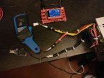
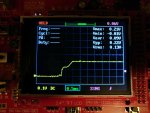
The issue with the equipment that you've defended here is that it "might" (read that as "will") miss information that you need to see. I get that you're only looking for a rough picture of what the supply is doing - but your DSO138 may not even give you that.
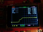
The DSO138 has a claimed bandwidth of 200KHz - The switching frequency of the converter you linked is 300KHz. When using a scope that has too low a bandwidth, it effectively acts as a low-pass filter for higher frequency noise. This means that the rapid spike of the current in the converter will likely be filtered or smoothed by the test equipment.
I.e. you might see a smaller spike than in reality, or no spike at all as the scope is only showing you lower-frequency components of it. This is dangerous in your case as you may be comfortable with the output on screen (on that toy scope) but in reality there still may be a spike that could quite happily kill your laser diode.
Trust me - it's near-impossible to properly measure the response of filters, or accurately understand what's going on in a Switch-mode converter when you have inadequate test equipment.
Ok so i might be able to see it or not , but i can't verify now because i dont have recieved everything.
What will happend if i use a 6.3v 3300uf(or more) capacitor after the load ? Will it smooth a bit ?


