Blord
0
- Joined
- Dec 24, 2007
- Messages
- 5,356
- Points
- 0
I have tried the reflection method from Cyparagon to reduce the power of the beam. I have mixed results of this method. My test laser was a mid power 445nm M140 diode.
Measuring directly on my LPM the output was 888mW. When I use a glass in 45 degree angle to the LPM the measurement depends on the axial rotation of the laser !
First I use both reflected dots on the sensor. The second dot came from the other side of the glass. This side creates a second dot.
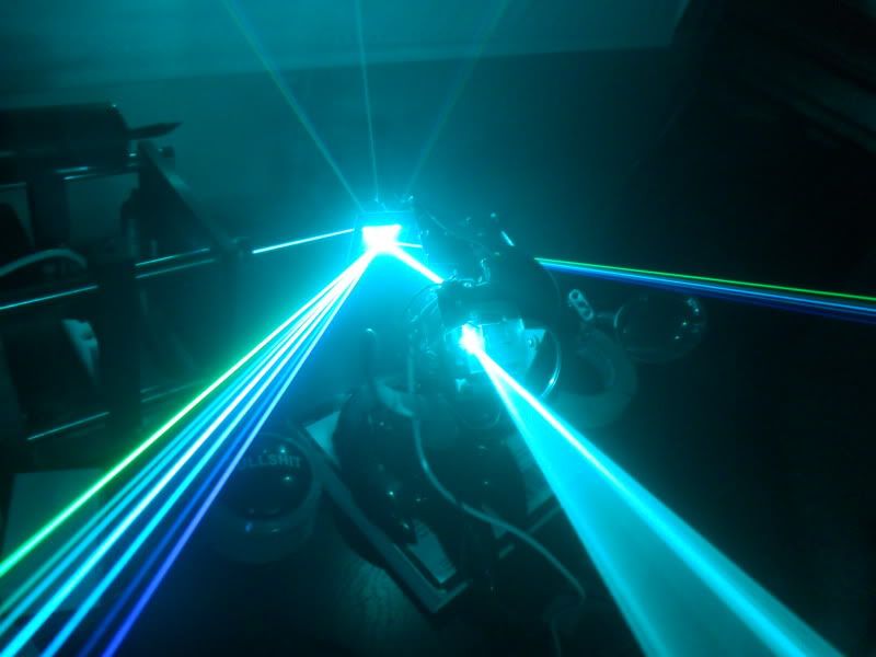
When the dot are in the vertical position the output is only 16mW. This is the setup in the picture.
But I rotate the laser 90 degree axially the output is suddenly 134mW !!!
The differences make the calculation very hard. A slightly turned laser could yield a different output.
Somehow the coherent nature of laser interfere with glass surface.
I think this method create an unnecessary factor in the LPM measurement.
Don't mind the LPM reading but look at the position of the dot.

Measuring directly on my LPM the output was 888mW. When I use a glass in 45 degree angle to the LPM the measurement depends on the axial rotation of the laser !
First I use both reflected dots on the sensor. The second dot came from the other side of the glass. This side creates a second dot.
When the dot are in the vertical position the output is only 16mW. This is the setup in the picture.
But I rotate the laser 90 degree axially the output is suddenly 134mW !!!
The differences make the calculation very hard. A slightly turned laser could yield a different output.
Somehow the coherent nature of laser interfere with glass surface.
I think this method create an unnecessary factor in the LPM measurement.
Don't mind the LPM reading but look at the position of the dot.