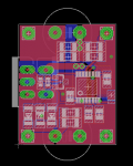
Here is my circuit:
(eagle brd and sch attached)
Its 25x50mm (~1x2 inch).
Vsense is 100mv, with current set by two 1206 resistors.
Depending on how many zeners you jumper it can use a Vin range of 3-30, 28-55, 53-80, or 78-105. Different voltages and currents will cause different part values to be needed. This calculator will help:
Switching Converter Power Supply Calculator
Its operating at 1mhz so Rhd you would need about 1uh inductor.
I got around the voltage limit by using zeners in front of the IC, and moving the sense resistors behind the load. I got around the switch current limit by using a small pchannel mosfet to repeat the signal and a big n-channel mosfet to handle the power (I'm about 90% sure this will work). The mosfet and diode are to-220 because they will have a lot of power going through them.
Ill test this soon. I have no idea if it will actually work as desired, so for now you should probably assume it has bugs. Usually the first try doesn't work perfectly and tweaks will have to be made.
I still need to do some small stuff on the board, like arranging component names and whatnot but the actual circuit is complete I have about all the components picked out on digikey. It should be a good general high power buck circuit. It even has soft start and easy access to the PWM pin.
I think you should go with 50 xml's over the 500W generic! My board should drive two strings of 25 from 4x 6s batteries.
70W in the driver will be the last of your worries.


