- Joined
- Jan 8, 2009
- Messages
- 3,144
- Points
- 83
^ dose it look like this ")
 :drool:


Follow along with the video below to see how to install our site as a web app on your home screen.
Note: This feature may not be available in some browsers.


Ehm .. guys .. feel really stupid to ask .. I'm sure it must be here somewhere .. but I just can't find it. So ..
Where do you buy drivers ? Also is there some DIY laser tutorial ? I built some stuff, but never a laser .. what should I pay attention to ? I hear these laser diodes are pretty easy to destroy.
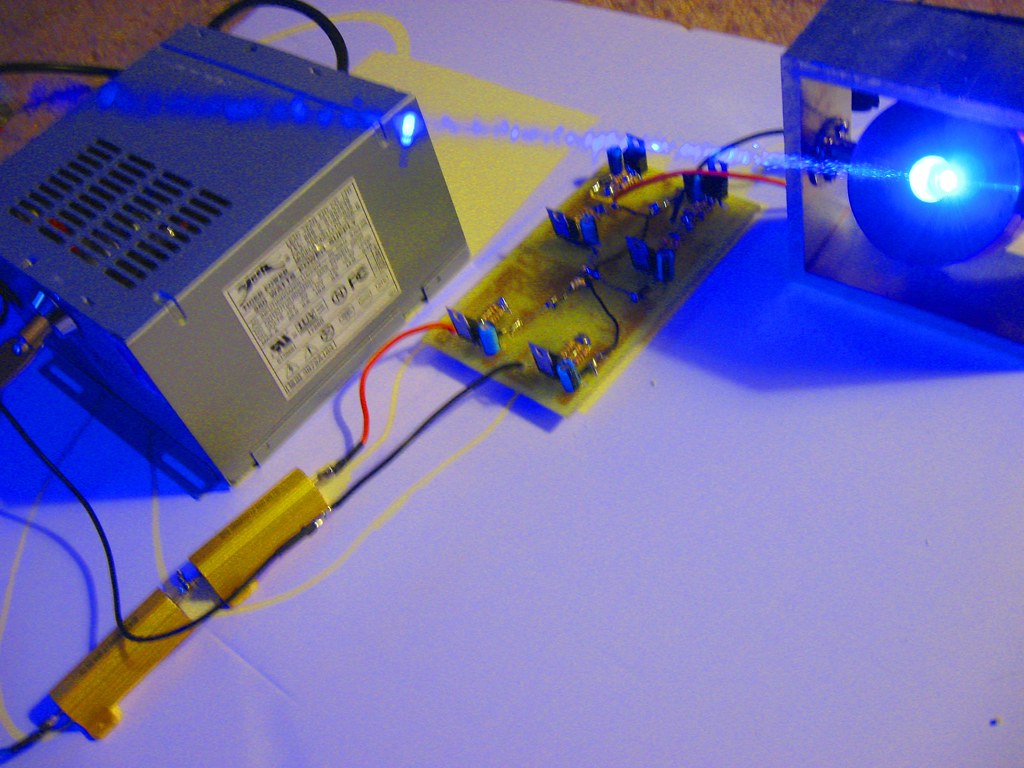
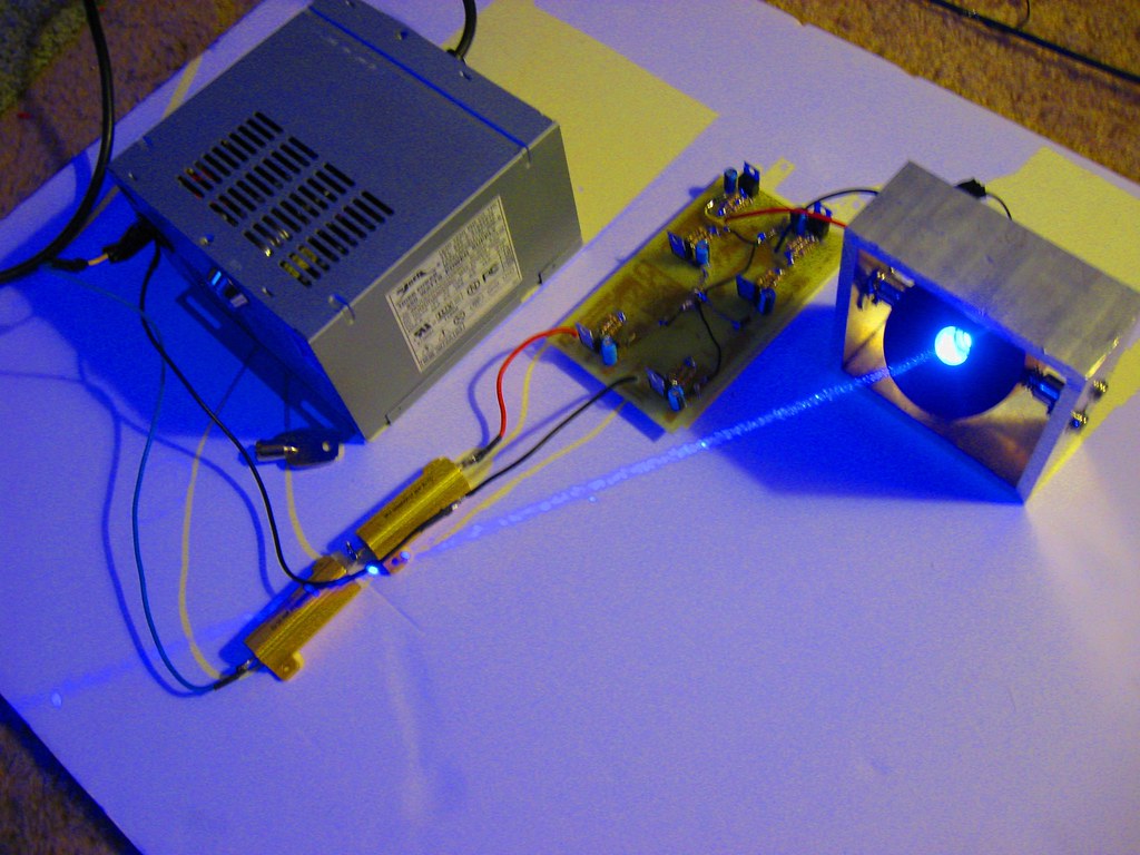
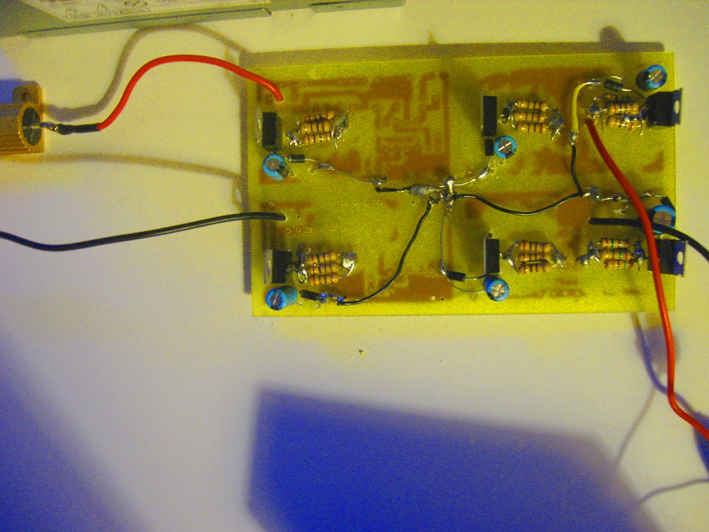
Ok, I'm running a bit behind on the labby. I finished securing all of the "many" unused wires from the ATX. Snipping unused wires short and putting heat shrink on the ends. I also found the "green" wire that energizes the circuit and tied one end to my installed key switch and a "black" ground wire to the other side. I had to cut a hole in the chassis to install the key switch. Hey, I'll be CDRH compliant to boot. I'll probably use the "violet" wire to install a "power on" LED, with a 330 ohm resistor in series to ground. I'm thinking about painting the drab gray chassis another color. Then I need to finish the 4 X DDL driver circuit board that it drives with 6.9 volts. I'll be shooting for 375ma per ddl driver(a nice low idle current level) so that I'll get 1.5 amps for the 445nm LD. I may install a high/low switch. Low would be 1125ma(3 ddl's switched on), which the LD can easily run at with 30 second duty cycles. And high would of course be 1500ma, which would be used cautiously until I can confirm that it wont kill the LD. ;-)
..... but any type can be good ..... if you have a big heatsink, you can also use schottky diodes, that have a dropout of 0,4V, so you need 10 of them, for drop 4V), that can be hooked easily on an heatsink, using their own insulating pads and plastic washers (the tab is connected to the central pin, so they need to be insulated from the heatsink). I couldn't think of the correct value resistors for a voltage divider with resistors, so maybe some heavy duty silicon diodes will work.