Welcome to Laser Pointer Forums - discuss green laser pointers, blue laser pointers, and all types of lasers

Buy Site Supporter Role (remove some ads) | LPF Donations

Links below open in new window

FrozenGate by Avery

DIY Portable fogger 18650 powered (picture heavy!)

farbe2

Well-known member
Joined
Oct 3, 2018
Messages
314
Points
63
Hello Guys!

I got my RGB Pointer and my Cryo Laser done. So I was searching for a new project.
Turns out you need fog to see beams well. Who would have known...

I was using a vaping device to produce fog before. First (while I was still smoking) it was very convenient. However I quit smoking and needed an alternative.
I modified the vape stick to include a fan that draws the air trough it. It worked but it was very messy, liquid dripping everywhere. I could not stand this anymore so I decided to build something better.

Born was the idea of a hand held smoke machine that uses 18650 cells and does not produce a mess.

I started by choosing a pump and thinking about a heater block.
I decided I would use a small cheap peristaltic pump and heating cartridges out of a 3D printer.
The heaters are designed for 12V @70W, I wanted to keep the form factor small and only use 2 18650 cells.
So I used two 12V/70W cartridges to get around 65W heating with a full charge and around 50W while empty.

I milled my first heater block and tested everything with just DC at the heaters and a syringe as a "pump".
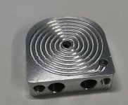
block.jpg
First tests where promising, way more fog that anticipated. Fogging up a small room to "cant see shit" took just about 5 minutes.


So I made up some PCBs and waited for them to get shipped:
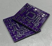
pcbs1.jpg


Looking quite nice already. I started the assembly process:
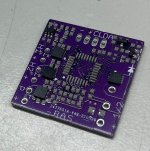
paste.jpg

First, using a laser cut stencil, solder paste gets printed on the PCBs.
Components are placed on top off the wet paste.
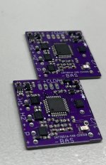
TopPlaced#.jpg

With everything placed, the pcb gets heated to solder temperature using a hot air gun. The paste melts and fixes the parts on the PCB.
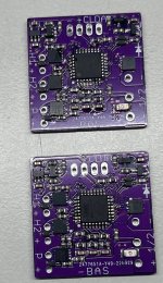
topSoldered.jpg

I needed to touch up some spots. I will clean that later. Next, the bottom side gets its paste printed and the parts placed.
A little soldering later, there are also some THT parts that need manual soldering.

Everything done:
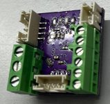
THTBack.jpg
finishedPCB.jpg

With the display soldered. Everything else gets connected:
- fire button with led for heating/ready
- encoder for menu navigation
- heating cartridges
- pump
- battery holder
- temp sensor
- finished heater block
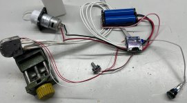
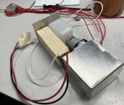
wholeSetup.jpg

Adding some software trough that extra ribbon cable shows that everything works as intended.
Just a little programming is left to do. I want to regulate the pump to very slow speeds. This is necessary to control the fog volume.

The menu structure makes everything adjustable.
I currently have set up:
- Controlling the fog amount (pump speed)
- setting the temperature and saving it
- different modes (continues - manual - interval with adjustable times)
- battery under discharge protection
- sensor fault detection

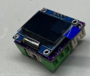
(quite hard to take a picture of the oled screen) I am a german native speaker, thats why the menu is in german.
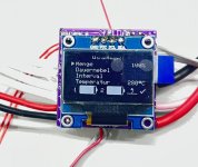
display.jpg

The board reads each battery state separately, this provides a safe way to determine the state of the battery.
If the battery gets close to over discharge, the board will disable one heater to limit the power draw and extend the runtime.
Some time later, the battery will be completely empty and the board will switch itself off.
A press on the fog button will turn it back on.
There is also a standby timer running. If the machine is idle and the standby time is up, the board will also turn itself off.

The display shows (bottom right) if both or just one heater is currently heating and if the set temperature is reached.

I still want to include some stuff like:
- regulating pump speed down if temperature gets too low, currently the pump just gets switched off
- adding a proper PID controller for the pump speed. I will use BackEMF to control the brushed DC motor

And a last picture showing some fog. Again hard to photograph. I will make proper pictures of the fog output later, this picture does not tell the whole story.
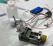
fog.jpg

Now I need to finish the software and get a case done.
Keep you updated.
 
Last edited:


I read something a while back about the fog juice needing to be vaporized at the correct temp. otherwise it can be unhealthy to breathe, of course all the wood smoke I make is likely unhealthy, as are so many things.
 
The vape juice is essentially the same as fog fluid.
A mixture of propylen glycol and glycerin.

Glycerin can make acrolein if heated in an oxygen free atmosphere.
This would be carcinogenic.
However that’s why normal fog machines use temperature control. The temperature is kept in a safe zone below 300C to prevent this decomposition.

I read that this occurres above 320C.
I limit the maximum temperature in code to 310C but I found that I get the best fog at around 280-290C. So I will keep it there.

I also know the taste and smell of decomposing glycerin. It happens sometimes inside the vape sticks as they don’t have any form of temp control.
And I can speak from experience: you would definitely notice a too hot running fogger. Disgusting smell and very bad taste. Hard to inhale too.
So i will keep an eye :D nose open for this distinct burning smell.
 
This is an awesome project. I would totally be interested in purchasing one from you when it’s done.
 
Nice work. I've considered before the idea of jury rigging a vape pen for getting quick smoke without having the warm up of a normal smoke machine. How long does you setup take to warm up enough to get fog?
 
I get around 3:45 min before its ready to fog.
If I wanted lower times, I would need to optimize thermal mass.
Or increase heating power.

I think there is some potential left.
I am currently at around 10g weight without the heaters.
With a thinner base plate and a thinner lid, there might be one g left on the table.

I am also running long wires between the controller and heaters. If I get the thing mounted in the housing, I will shorten that. This should result in slightly lower voltage drop and therefor higher heating power.

I might also be getting lower heating power because the elements have a slight PTC.
So gluing them in the blocks might help. (decreasing thermal resistance) I will do that while finishing the case.

More heating power isn't really possible without increasing battery number or changing type.
I currently use Samsung INR18650-35E these offer around 10.5Wh at 8A rated discharge current.
This is almost the best cell for this application.
I need around 8A discharge continues.

This would give me around 25min of full fog output, way longer with lower outputs

Taking more than 8A out of these cells would lower the efficiency and other cells that can deliver higher currents have lower Capacity ratings.

So its just a tradeoff.
 
I expect you're going to want a larger battery pack, 8A continuous from 2 x 18650's is a lot, the voltage will sag @ 8A and the cells will discharge quickly because the Wh rating is calculated at an optimal discharge rate, so a 10.5Wh battery may give you 1/2 an amp @ 3.5V for 6 hours, but not quite 1A @ 3.5V for 3 hours and drawing 8A @ 3.5V you might expect 20 min but only get 5 minutes because it's not linear and the higher the draw the faster your cells will discharge.

I would be surprised if you can get 8A @ 3.7V or 8A @ 7.4V from 2 x 18650's in series for 25 min. continuous, it might be only 5 minutes at 8A continuous from a full charge and with new cells.

What I'm saying is your cells might be rated at 8A max continuous discharge and 10.5Wh capacity which is a lot actually, most are 3.5 -4.5Wh or 3500-4500mAh

Actually the Samsung INR18650-35E is 3.5Wh or 3500mAh rated. So at 8A you won't even get 5 minutes continuous.

A Samsung INR18650-35E might do .35A for 10 hours but not 3.5A for 1 hour and never 8A for 25 minutes, at 8A I doubt you will even get 5 minutes continuous.

 
Last edited:
8A continuous from 2 x 18650's is a lot
Mhm thats actually not quite true.
The Samsung INR18650-35E is rated for 8A continues discharge current.
There are cells that can do much more. The Sony VTC6 for example is rated to deliver 30A continues if you keep the temp below 80°C or 15A continues without temperature cutoff/protection.

You also mixed up Wh in Watt hours with Ampere hours.
Wh describes the complete energy thats inside the cell. It includes the voltage sag as the cell gets discharged.
Any cell that offers more than 3500mAh inside a 18650 package is just a lie. There are no cells that can do that. *currently!*

The Samsung actually does around 12.5Wh at 0,2A discharge current. As the mean voltage is around 3,55V and it puts out around 3,5Ah.
If the cell gets discharged harder, there is some voltage drop on its internal resistance. This reduces the voltage, therefore the total energy that can be extracted out of this cell.
The samsung cell measures around 35mOhm internal resistance. This reduces the voltage by around 0,28V at 8A discharge rate and will produce around 2,24W powerloss inside the cell. As the discharge time would be around 26min for this load, it would equate to around 1Wh of lost energy. This makes sense. My quoted 10.5Wh @ 10A discharge adds up to this. (around 12.5Wh @ 0,2A - 1Wh loss at 8A = 11,5Wh)

I also did the tests and it works out quite good. I get a little more than 30min runtime. Thats also be expected. The current will drop with longer use times as the battery voltage gets lower. This reduced current and therefore extends runtime.

I implemented a little feature in software: As i use two heaters, i can heat with just one if the battery gets close to empty. This keeps the voltage higher as the current is lower. This also extends the runtime.
This heating mode also gets used when there is little to no fog needed and one heater is sufficient to keep the temperature up. This reduces I²R losses inside the battery and wiring, further increasing runtime.

And you dont need to take my word on it.
There is a test site that measures almost every 18650 cell available.
Here are the quoted cells:
Sony VTC6
Samsung INR18650-35E
This site shows graphs for every cell at different currents.
For the Samsung cell, there is even a runtime graph at 7A which shows 28Min.

There is even a comparison tool:
Comparison tool
 
Last edited:
Seems like you're working those 2 cells really hard and I don't know how many charge cycles you will get if you run them all the way down under that 8A load, I typically recharge when my cells get down to 3.3 - 3.4V also you are talking about brand new cells.

Your boosting your 7.4V to carry 70W heaters at 12V, so basically 6A and maybe more than 8A battery draw as they discharge and the voltage sags even harder, then as your cells age which could happen at an accelerated rate as you would be working them awful hard, your capacity will be less.

I suppose with those cells, being brand new, that it's possible to get 25 min. if you run them pretty much all the way down, but it still seems like your working them really hard.
 
I used one 3x set of VTC5 cells for quite some time now. around 4 years to be exact. They have seen there fair share of abuse and high currents. I used them in a vape device and was drawing around 5A. I recharged almost daily.
These cells still average a capacity of around 2200mAh (originally 2,6Ah).
I also used some random power tool cells that i got out of an old drill battery. They are Sony VT cells. These also held up well.
Some Samsung 25R cells also did quite good.
I must have had > 1000 combined cycles on these cells. All quality cells held up very well.

Samsung states in there datasheet:
>500cycles to reach 60% capacity, each cycle is 1A charging current with 3,4A discharge current, discharge down to 2,65V!
Thats a very low discharge voltage. I switch off at 2,95V@ cell.
High discharge currents dont damage cells as much as one would think.
Storing them at high voltages/temperatures, charging at low temperatures and high currents are the real cell killers.

To be fair, 500cycles in this machine would be around 250h of constant fogging. Ok i will not reach that as capacity will be degraded. Lets say 200h fog time in total before i need to change these cells.
Thats likely multiple years of usage.

I will say:
Yes i run these cells hard! Very hard indeed, that what they are made for.
They last under these conditions perfectly fine. I pay for them, so they have to work for me. No free lunch :D

Powertools use way more current and abuse there battery way harder. (storage at low voltages, low temperatures, hot temperatures, fully charged storage and so on)

Regarding the heaters:
I think i didnt make this clear. I use heaters that are designed to be used at 12V and draw 70W there. So thats around 2,05 Ohms.
I get around 1,025R load resistance if both heaters are on.
I use two of these heaters with the raw battery voltage. No stepUp here.
Calculating power, i get: V²/R = W
8,4V² / 1,05R = 68W
6V² / 1,05R = 35W
so around 50W mean power between fresh of the charger and completely empty.
That also explains the longer than calculated runtime. The power drops significantly at the end of battery life.
Not really a problem, just little lower fog volume.
 
Hello Guys,

i got some work done.
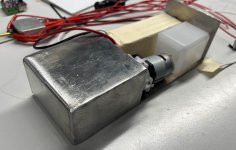
I started to build a housing for one of my machines. It uses a different battery and a housing thats just as high as needed.
Thats because i want to fit the machine in a very small (hight wise) space thats plenty wide/long.

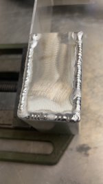
I started by bending and welding some aluminum plate. The case will hold a small tank and the battery.
I used 4 pouch cells with 2,2Ah each. The arrangement is 2s2p. This gives me 4,4Ah or 33Wh. Thats a bout 1/3 more than two 18650 cells could supply.

I did not make pictures of the bending part.
I just used some 75mm wide 60cm long 2mm thick sheet stock and bend the front u-shaped.
The u part is 43mm high.
I then shortened the stock and bend the back up.
The now open sides got pieces made and welded in.
IMG_1401.JPG
Yes yes, i know. I am not a professional welder. It holds together and thats what i need.

Grinder and paint make me the welder i aint.
IMG_1400.JPG

After a little grinding, everything looks quite nice.

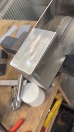
I finished both sides and placed the parts inside the half finished housing.

IMG_1399.jpg
IMG_1398.jpg

Next part:
I think that i will 3D print a u-shaped lid for the housing that also takes the display and buttons.
Or i make it out of aluminium. I need to think about that.

Good enough for today.
-Farbe
 
Hello Guys!
Sadly i forgot to take pictures of the build process. So i will only write what i did in the meantime:

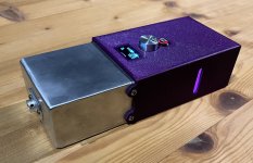
I drilled a holes for the fog output and cut some threads to fasten a "nozzle" and the case-lid.

Next step was drawing the case lid and printing it. I got some issues with my printer and needed to reprint the lid multiple times.
Some additional programming, testing and wiring later, everything found its place inside the case.

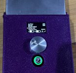
First the user interface:
As described before, i use a rotary encoder, display and a illuminated button to control everything and display states.
The menu is in german and features a continuous, manual and interval mode. The temperature is also adjustable.
Pressing the knob selects a menu item. Turning it adjusts its value.
The bottom row of the display is reserved for status icons. It displays the battery state and if one or both heating elements are active.
It also shows if the set temperature is reached, this is also done by changing the button color from red (still heating) to green (ready).
The button also flashes if the machine is working. e.g. if its currently in the off state of the interval mode or continuously fogging is enabled.


UI.jpg

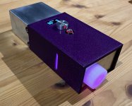
The tank is illuminated by a nice pink led that matches the case color, that makes fluid level checks easy.

front.jpg

To fill fluid, there is a screw on cap on the back. The small hole in the middle is a one way valve to let air in while fluid is pumped out.


back.jpg

All ports are on the left side.
The small headphone jack is used as a remote trigger. It mirrors the functionality of the illuminated button.
Disabling and enabling of fog in every mode. That way, i can easily add a foot switch to control the machine hands free.

connector.jpg

The big 4-pin connector is used for charging and for connecting a fan. The machine includes a fan controller with configurable speed.
The fan is automagicly enabled while the unit is fogging.
I use it to distribute the fog evenly in my room. It helps tremendously.


fan.jpg


The fan offers pass trough. I can charge the machine, use the fan and fog at the same time. This gives unlimited runtime.


One might ask: what can this thing do, its small, so it cant put out much.
Oh how wrong.
Have a look at this video. The machine is running in interval mode to give me time to step back.
5 Minutes at this output level is way to much for a small room.


so long
farbe


Back
Top