roSSco
0
- Joined
- Dec 5, 2007
- Messages
- 649
- Points
- 18
Just think of it as Watts and you're all set.LarryQ said:Can that display be set to drop off the . (point)??
So that it reads 000 instead of .000 or 174 instead of .174???
Thanks....

Follow along with the video below to see how to install our site as a web app on your home screen.
Note: This feature may not be available in some browsers.
Just think of it as Watts and you're all set.LarryQ said:Can that display be set to drop off the . (point)??
So that it reads 000 instead of .000 or 174 instead of .174???
Thanks....
LarryQ said:Hey Knimrod,
I PM'd you..but after thinking about it ..I thought that the info would be helpful to others.
Can you answer a couple of questions for me?
1) Can that display be set to drop off the . (point)??
So that it reads 000 instead of .000 or 174 instead of .174???
2) The 5 dip switches, What switch settings did you use on this display??
3) It's easy to see where you tap for the output to the meter, but where do you tap into the circuit to get the power for the meter??
At the +9V side of the power input and the GND, where they connect to the board???
Thanks for the clarification.
Larry
Thanks....
That's what I was going to do this evening. ;Dknimrod said:My meter showed up today.
A couple of things. Be careful and double check everything. The connector that came with my meter was wired backwards as the wire colors were all reversed in the connector according to the manual. Not a big deal to fix, just pull the wires and reinstall in the correct order.
The dip switch works as follows:
Positions 1-3 set the decimal place. If you want no decimal point, set 1-3 "off". If you want a decimal point to the right of the most significant digit, set 1 "on". 2 & 3 "off".
Position 4 selects the ground mode. For a common ground (which is what we want) , set 4 "on".
Position 5 selects the meter resolution/range. Set 5 "off" for 1mV resolution (0-1.999V range) or set 5 "on" for a 100mV resolution (0-199.0V range)
So... for the meter to display as 0-1.999 Watts, set the dip sw.: 1=on, 2 & 3=off, 4=on, & 5=off
for the meter to display as 0-1999 Milliwatts, set the dip sw.: 1-3=off, 4=on, 5=off
Here's how the connector should be wired (top to bottom):
(1) O - Red ----------- Switched Battery 9V+
(2) O - Black --------- Ground (Battery)
(3) O - Blue ---------- Amp Signal +
(4) O - Green -------- Amp Signal -
This can be a 3-wire hook-up if you hook pins 2 & 4 together (black and green) and connect to the amp out- , pin 3 (blue)to the amp out+, and pin 1 (red) to the switched 9V battery + on the toggle switch.
This meter and back light draw about 30mA which will be fairly easy on the batteries.
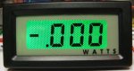
I was also able to remove the "V" which appeared to be silk screened on the display by gently scraping it off with the end of a steel rule. I then applied some dry transfer lettering to indicate the appropriate units.
positron said:roSSco,
I'm in Perth Western Australia. I think I would like to grab 2 of these if I can. I really appreciate your help mate![]()
roSSco said:[quote author=positron link=1200112201/135#141 date=1202117889]roSSco,
I'm in Perth Western Australia. I think I would like to grab 2 of these if I can. I really appreciate your help mate![]()
toked323 said:heyh knimrod what is the over all estimated price? and any picts of the circuit board only ?
thanks,
toked
toked323 said:heyh knimrod what is the over all estimated price? and any picts of the circuit board only ?
thanks,
toked
knimrod said:[quote author=toked323 link=1200112201/150#154 date=1202177437]heyh knimrod what is the over all estimated price? and any picts of the circuit board only ?
thanks,
toked
amkdeath said:very nice, can wait to assemble mine!
BTW, where does the GND on the PCB get connected to??