Welcome to Laser Pointer Forums - discuss green laser pointers, blue laser pointers, and all types of lasers

Buy Site Supporter Role (remove some ads) | LPF Donations

Links below open in new window

FrozenGate by Avery

DIY Laser Power Meter Interface Module

IgorT said:
What about the interface board? Do you have this as well?
yes.
actually bought the kit for that one... for the power amp I made my own pcb using the circuit diagram, and used parts off the original detector's board.

ok now, i'm offline for a while :P


Aren't there any Kenometer users, that would like a computer interface?

Maybe they don't know about it?
 
IgorT said:
Aren't there any Kenometer users, that would like a computer interface? Maybe they don't know about it?
how about making a new topic, with "Kenometer Owners Notice" as the subject?
 
i dot mine all soldered and ready to go, but I am confused, where EXACTLY do the +9v, -9v, GND, the other GND, sig1 and sig 2 get connected to? is this 18v in or 9v in?

im confused


amk
 
knimrod said:
The cap modification would go on the original amplifier PCB as pictured above. But I'm not sure it's necessary yet..
I'm looking into some simple software filtering.
nvm, found this, but is it the full 18v? so input on interface is in parallel with the input to the LPM board?
 
ok, I got it working, i used my USB serial bus, which is basicaly serial in, usb out to computer. it works fine.

I did not install the .1uf cap on the LPM board yet.

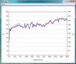
When I click on view graph, it gives me a red and a blue line, what do they stand for?


EDIT I installed the cap, and i must say, DO NOT USE THE INTERFACE BOARD WITHOUT THE CAP ON THE LPM BOARD!! This SUBSTANTIALLY reduced noise. but it didn't eliminate it...

what do I do to calculate my own gain?

also, the readings on the Interface program are higher than the reading on my DPM. the gap increases exponentially, at 10mW on the DPM, for example, the interface shows 12-14, (doesn't stop on a single number). but at 260mW on the DPM, the interface program shows 290...

which one do I trust?


amk
 
The difference between 10 and 12 is 20%. The difference between 260 and 290 is about 12% I suspect if you make more careful measurements, the difference will be closer to the same. Make sure your soft zero is set properly also. If it's off, the low numbers will show a bigger error. Set the "gain" so that the numbers track across the measurement range you're looking at.
 
why do my graphs come out like this: (attatched)

I dont get what the 2 different lines stand for...


Im liking this thing sooo much....
 

Attachments

  • graph_003.jpg
    graph_003.jpg
    45.3 KB · Views: 113
If you built the interface in the standard configuration, you have two channels, each with a different range.. One range is 0-1000mW (red) and the other is 0-4000mW (blue). The overall power will indicate the same between the two but the resolution of the 4000mW (blue) channel is 1/4 of the red channel. Since you are probably not going to be measuring any >1000mW lasers, I would recommend just setting the gain for the second channel to '0'. This will make the blue channel not display.
 
One of my RGB setups is rated at 1.7 watts so this is a biggie for me. I never seen a clarification of the voltage input r'qments. Please elaborate on this a bit as well as the signal input voltage. I did get my kit today....Thanks!!!! I will proceed after getting more details from you on these topics.
 
bluephoton said:
One of my RGB setups is rated at 1.7 watts so this is a biggie for me. I never seen a clarification of the voltage input r'qments. Please elaborate on this a bit as well as the signal input voltage. I did get my kit today....Thanks!!!! I will proceed after getting more details from you on these topics.


The output from the DIY amplifier is 1V = 1W. Because the AD converter has a full range of 0-5 volts, we need to optimize the DIY amp's signal with the interface module's AD converter input range. There are two inputs on the interface module that make up two channels of operation. The idea is to optimize the range of the AD converter (0-5V) with the range of power you want to measure (0-1W or 0-4W). In the standard configuration, the interface inputs are common but the two channels have different gains in their respective amplifiers. The channel 1 amplifier has a gain of 5 to yield 0-5Volts for 0-1W of laser power. The second channel has a gain of 1.25 to yield 0-5volts for 0-4W of laser power.

For measuring 1.7 Watts of laser power with the interface, you would use the second channel for your display. It will have a range of 0-4W with a resolution of 4mW.
 
my vid of the power meter+interface module

[media]http://www.youtube.com/watch?v=agTq5NBeXX0[/media]
 
Nice work Amkdeath!

Can't wait to get my interface board. BTW, what kind of batteries are you using in that red?
 
How powerfull is it when the 317 is still regulating?

I'm currently making a ~300mW out of an 1AA MXDL, using two 1/2AA Li-Ions. The heatsinking might be complicated, but i think it should work.
Before i had a meter i didn't even bother trying to use the open can. Now i will at least see the difference..
 
Recieved my Interface-Kit today!! ;D ;D ;D
Now to find time to add it to my LPM ::)
Thanks a billion Knimrod!!
Dark Horse


Back
Top