
Welcome to Laser Pointer Forums - discuss green laser pointers, blue laser pointers, and all types of lasers
How to Register on LPF | LPF Donations

Navigation
Install the app
How to install the app on iOS
Follow along with the video below to see how to install our site as a web app on your home screen.
Note: This feature may not be available in some browsers.
More options
You are using an out of date browser. It may not display this or other websites correctly.
You should upgrade or use an alternative browser.
You should upgrade or use an alternative browser.
DIY Homemade laser diode driver
- Thread starter Daedal
- Start date
- Status
- Not open for further replies.


jayrob
0
- Joined
- Sep 21, 2007
- Messages
- 9,862
- Points
- 113
trublu832 said:Hello all, here is my first attempt at a driver circuit board. I should be receiving a laser diode soon to use in conjunction with it. Thanks for all of the schematics and tips.
First attempt! Man, that's really clean looking. Good job. Since it's your first one, just a recommendation if you haven't already done so, (and for new ones too) make sure you test continuity on the connections with your DMM. Also, make sure stuff that is not supposed to touch, isn't touching...
Jay
http://www.laserpointerforums.com/forums/YaBB.pl?num=1186966870/291#291
- Joined
- Feb 23, 2008
- Messages
- 2,832
- Points
- 48
can some1 explain testing the drivers a little better. ive connected the 2 leads to a 1ohm resistor and the dmm is set to mv but i get O.L(overload) whenever i turn the switch on. adjusting the pot seems to have no effect. im usin the multimeter(datasheet) below:
http://www.extech.com/instrument/products/000-099/datasheets/22-816.pdf
http://www.extech.com/instrument/products/000-099/datasheets/22-816.pdf
ndrew2505 said:can some1 explain testing the drivers a little better. ive connected the 2 leads to a 1ohm resistor and the dmm is set to mv but i get O.L(overload) whenever i turn the switch on. adjusting the pot seems to have no effect.
Ya I second that one, a couple nice macro pics or a vid tutoriol would be outstanding!! Please!!!
- Joined
- Aug 25, 2007
- Messages
- 2,007
- Points
- 63
usafsgc said:There's 58 pages, and Ir eally don't want to look through all of them, but what changes would I need to make to the driver if I wanted to use a blu-ray diode?
In the most basic terms, just the input voltage and the sense resistance. A Blu-ray needs a higher breakdown voltage, so 9V is a good target. They don't draw much current, so a typical rectangular battery is just fine, easy, and cheap. They also need less current, so the resistor across the LM317 needs to be of a higher value. Others have used a "sweet spot" of a 33ohm resistance, which will give you around 38mA through the diode (1.25V of the LM317, divided by 33ohm, I = V/R). Other than that, every thing else should be the same.
For testing the set-up, 4 diodes is no longer appropriate (that's ~2.8 V). You need a higher voltage to match the Blu-Ray load. I haven't done such a test, so I can't personally recommend anything specific, maybe someone else can help you out with it, but I might guess using 8 silicon diodes in series might work (~5.6 volts). But don't hold me to it
")
D
Deleted member 8178
Guest
I used 6 red leds like this [smiley=smiley_down.gif]
l ---l>l----l>l----l>l---l
-----l l----
+ l ---l>l----l>l----l>l---l _
l ---l>l----l>l----l>l---l
-----l l----
+ l ---l>l----l>l----l>l---l _
Quick question, how hot doest the LM317 heatsink get? I just notice my get real hot to where it hurt if I leave my finger on it for more then 5 seconds. Is this normal or is it shorting some where? Every thing is working normally, with the red laser at 416 mA.
- Joined
- Feb 23, 2008
- Messages
- 2,832
- Points
- 48
so in order to increase the mv/ma coming out of the drivers i can just lower the resistor value right?
to answer the ? above it just depends on how many ma/mv is coming out of it. the higher the ma/mv the hotter it gets.
to answer the ? above it just depends on how many ma/mv is coming out of it. the higher the ma/mv the hotter it gets.
tiedyeguy said:on trublu832's post on pg.57, where are the pos+ Neg- wires to the LD and the power source connected? Also, what kind of resistor and what kind of pot. are you using on that?
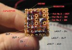
The power in and diode wires are the two sets of red/black twisted wire coming off of the board, i'll attach a picture for some more detail on how everything is connected in the small space. The resistor is 3.9 ohm and the trimpot is 25 ohm.
I received my laser diode and I powered it up just to test it and it all works, now i've put the project on hold until I get my laser goggles.
")
Attachments
")
- Joined
- Feb 23, 2008
- Messages
- 2,832
- Points
- 48
for blu-rays do i just add the 33ohm resistor or is there anything else you need to change?
- Status
- Not open for further replies.