Welcome to Laser Pointer Forums - discuss green laser pointers, blue laser pointers, and all types of lasers

LPF Donation via Stripe | LPF Donation - Other Methods

Links below open in new window

ArcticMyst Security by Avery

DIY Homemade laser diode driver

Status
Not open for further replies.

Gazoo

0
Joined
Jun 9, 2007
Messages
3,206
Points
38
woop said:
Wait a sec. are we talking about resistors for use as a shunt, for measuring current or the sense resistors for the LM317?
for the 317 sense resistors, you are right about the 1.25 voltage.
I thought we where talking about shunt resistors for measuring the current...

I don't know what you mean by a shunt resistor...don't they go in parallel with ammeters? What we are talking about is simply placing a 1 ohm resistor in series with the diode. However as I stated twice, I did it a bit differently and put the resistors between the output and adjust.

Added..Nevermind...the term shunt resistor is correct in this application as well as many others...sorry.


woop

0
Joined
Nov 9, 2007
Messages
342
Points
0
I was refering to what IgorT said before,

IgorT said:
BTW: There is also a better and more exact way of measuring current here..

You can put a 1/2W, 1 Ohm resistor in series with the LD.. Then you measure the voltage drop (in millivolts) across it, and the voltage drop in mV is equal to the current in mA.

It will not affect the behaviour of the circuit in a bad way. It will have to put out slightly more voltage, but not much.

This is also safer than putting the multimeter in series, since you don't have to disconnect the LD, or anything else..


It can also be done with a different value resistor, but you would have to calculate the current (I = U / R) and the voltage drop would be higher..
what he is talking about is a shunt, separate from the lm317
I attached a picture of what he means (and what i have been talking about)
 

Attachments

  • LDshunt.png
    LDshunt.png
    5.7 KB · Views: 1,308

woop

0
Joined
Nov 9, 2007
Messages
342
Points
0
oh yeah and with your resistors getting hot. even if it is a 3W resistor it still needs to dissipate the same amount of energy, so while it might take a bit longer to heat up because of its size, it will still get hot, unless you put a heatsink on it.
 

chimo

0
Joined
Jun 20, 2007
Messages
650
Points
0
I hope everyone realizes that the schematic pic is not a constant current source. The load must be connected to the Adj pin for that.

There is no need for a shunt resistance, either - the sense resistor can be used for that. There is negligible current sink into the LM317 from the Adj pin so just measure the voltage across the sense resistor (the resistor between Out and Adj) to ensure the cct is still in regulation ane caluclate the current by: I=1.25/Rsense

woop said:
I was refering to what IgorT said before,

[quote author=IgorT link=1185701612/510#522 date=1194819488]BTW: There is also a better and more exact way of measuring current here..

You can put a 1/2W, 1 Ohm resistor in series with the LD.. Then you measure the voltage drop (in millivolts) across it, and the voltage drop in mV is equal to the current in mA.

It will not affect the behaviour of the circuit in a bad way. It will have to put out slightly more voltage, but not much.

This is also safer than putting the multimeter in series, since you don't have to disconnect the LD, or anything else..


It can also be done with a different value resistor, but you would have to calculate the current (I = U / R) and the voltage drop would be higher..
what he is talking about is a shunt, separate from the lm317
I attached a picture of what he means (and what i have been talking about)[/quote]
 

brando

0
Joined
Nov 13, 2007
Messages
10
Points
0
hi all- really cool forum here, got me all excited :) i had to go and buy 2 diodes from senkat, rip apart bunches of old electronics for various parts (incl diodes) and then visit the electronics store :) It sure is fun, but I am such a noob at electronics.... that's why I write for help now-

I've successfully built one of these drivers and I'm working on the second now, making it more compact than the first. It is essentially identical in parts, except for a smaller pot (100Ohms 0.5Watt precision trimmer vs. the large 3Watt Rheostat I used on the first). Anyways, when I hook up an LED, it doesn't light. My multimeter is showing 5.18 Volts going to the LED (My first driver shows 3V to LD). I don't know how to measure current :( I can't see any shorts on my solder job. Could the LM317T be fried from too much heat while soldering?

would appreciate any help-
Brandon
 

brando

0
Joined
Nov 13, 2007
Messages
10
Points
0
i think i found my problem... looking at aaron's diagram with pics, i see the middle pin on the 317 is OUT, not ADJ, as it appears it might be in the diagram from page one of this thread... trying that now...
 

brando

0
Joined
Nov 13, 2007
Messages
10
Points
0
i've corrected the pins on my 317-

the LED now works

but I am still getting too many volts- fluctuates between 4.5 and 5.11 without an LED attached...  with an LED it reads 2.7v, with an LD 1.8v... running off 4x AA batteries (almost new)

so is my 317 toast?
 

brando

0
Joined
Nov 13, 2007
Messages
10
Points
0
ok, let's go for the most-posts-by-a-noob award ::)

so i read a little on Ohm's Law in wiki and then turned my pot all the way up... bingo :-[ got laser :cool:
 

IgorT

0
Joined
Oct 24, 2007
Messages
4,177
Points
0
brando said:
but I am still getting too many volts- fluctuates between 4.5 and 5.11 without an LED attached...  with an LED it reads 2.7v, with an LD 1.8v...  running off 4x AA batteries (almost new)

This is exactly the same question that was posted a page or two ago..


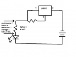
The circuit regulates the current by giving the load just enough voltage, for this current to flow through it.

The circuit CAN NOT regulate the current without something for the current to flow through. This is why it gives out the maximum voltage it can (without load) and you get a reading that seems too high..

When something is attached to the output of the circuit, it will automatically adjust the voltage, to achieve the desired current. This current will then stay constant, but the voltage will drop slightly, when the LD gets hot and drops in resistance.


BTW: Powering the circuit up without a load will charge the capacitor to the voltage you mentioned (around 5V). If you then connect the LD to the circuit, the capacitor might still have enough charge in itself, to damage or kill the LD. This is why it is recommended to short the capacitor, before soldering the LD to it.. After that it is best never to remove it again.

Luckily capacitors self discharge quite fast, but it's better to be safe. Powering the circuit up without a load serves no purpose whatsoever.


EDIT: Oh, and not to forget, LEDs have a different forward voltage then LDs. If you simulate the load with a few LEDs in parallel, you will be able to verify if the current regulation works, but the voltages will be different then on the LD at the same current. Since it regulates current by adjusting the voltage, this is what's supposed to happen, and it means it works.
 

brando

0
Joined
Nov 13, 2007
Messages
10
Points
0
yeah, i feel like i've read every post in every thread two or three times... in the heat of the moment though, you know :) a lot of learning yet to do ;D

thanks very much for the insight!
 
Joined
Aug 15, 2007
Messages
790
Points
0
IgorT said:
[This is exactly the same question that was posted a page or two ago..

I understand that this is the longest thread on the forum, but why don't people just read it? Had everyone who posted taken the time to read the entire thread first, I doubt it would be even half as long.
 
Joined
Jul 24, 2007
Messages
2,749
Points
0
:) I guess in many ways it is easy for members who have been watching this from the get go, we've been there, done that and got the working laser to proove it.....

The most important info is in the first few pages anyway so reading every post is not imperitive....but there is worthwhile stuff in the rest of it if you keep at it.

Regards rog8811
 

woop

0
Joined
Nov 9, 2007
Messages
342
Points
0
also i think everyone should have a quick look through the datasheet before posting questions. it even has the schematic for a constant current source. along with correct pinouts.
yes it would help if daedal's schematic didn't have the wrong pinout. another reason why you should all read the datasheet
http://www.national.com/ds.cgi/LM/LM117.pdf

geez even a far back as the 3rd page there are people asking stupid questions that where already answered.

the thing with using a shunt is that it is easier and more acurate. also it doesn't waste much voltage.
 

Gazoo

0
Joined
Jun 9, 2007
Messages
3,206
Points
38
woop,
I agree except I don't consider any question to be a stupid question. Many members are new to this forum and also new to electronics. I have noticed as members get seasoned and learn then they help others. In addition the numbering on Daedals' schematic is very confusing. People think it is correct so they just go from it and don't know to look at the datasheet. I believe this has been the cause of a lot of problems in this thread.

As far as the shunt resistor, I fully agree. Sure it is easy to calculate current as chimo suggested, but I like to always have direct readings when I am turning that rheostat looking for the threshold of my lasers...lol. Especially the blu-rays as there is very little room for error.

Every day I come here I learn something new. If members didn't ask questions I would not be learning anything. Sometimes I make mistakes with my answers and I will be corrected, as you know. Then I will go and verify and admit when I am wrong. I think we all need to be tolerant of each other. Tolerance and patience is one of the very many great things about this forum.. :)
 
Joined
Aug 15, 2007
Messages
1,880
Points
0
this thread may be coming to an end... sorry DDL! ya i told daedal first... and he's cool.
but with my development of a driver for Kenom's barrels, I may be able to supply assembled drivers or kits for less than it costs to do it yerself.
Low dropout reg, so you can use only 5.5v for blurays or as little as 4.5v for reds...
and on a professionally printed PCB.
This is only a very vague maybe at the moment, i have to run it by kenom and drlava, the other members of the development team, and i have to see if its financially viable for me to sell them straight off or if it needs to take a GB format. But we're looking at $5 a pop, ISH. very vague like i said.
 
Status
Not open for further replies.


Top