Welcome to Laser Pointer Forums - discuss green laser pointers, blue laser pointers, and all types of lasers

LPF Donations

Links below open in new window

ArcticMyst Security by Avery | Browser Hide by Avery

DIY Homemade laser diode driver

Status
Not open for further replies.

danq

0
Joined
Sep 18, 2007
Messages
835
Points
18
I've gotta be somewhere soon, so can't respond fully (I'm a slow composer) but just wanted to at least make the point that it was the LD's effective resistance at that voltage/current. Its "resistance" is kind of slippery.
:-?
...and basically, the reason for not using an ammeter is insertion loss - you'll find that your meter introduces resistance to the circuit, varying depending on what range it is on. That's because your meter is measuring voltage across an internal resistor!


IgorT

0
Joined
Oct 24, 2007
Messages
4,177
Points
0
danq said:
...and basically, the reason for not using an ammeter is insertion loss - you'll find that your meter introduces resistance to the circuit, varying depending on what range it is on. That's because your meter is measuring voltage across an internal resistor!

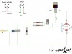
That's ok, i don't use a multimeter in series anyway, i can see the current (and can limit it if needed) on my lab PSU.


Well anyway, yesturday i finally managed to make my FIRST working laser!!!


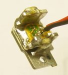
I used the LD from the Samsung TS-H552 version B, (16x DVD+R/12x DVD-R..... i'm saving the version U for later, hoping it's stronger)

These are unfortunatelly soldered onto one chunk of metal, which is then soldered onto another one that is then screwed into the optical assembly of the drive..

I only removed the outer chunk of metal (using a dremel - trying to unsolder it would probably kill it, since i would have to heat EVERYTHING, including the LD, up to the solder melting temp.) and attached some heatsinks to the inner chunk of metal... Since it's soldered it dissipates heat very nicely..

I had to get creative with the lens assembly, but i FINALLY managed to get a WORKING laser!

i went up to 280mA, but am guessing it could do even more.. It hardly even heated up... And there's still a Peltier in my drawer... ;)

Finally a visible red laser beam! Feels great! I can't wait till i get the AixiZ modules, to make it all even better...

Thanks to everyone for your help and ideas! I really appreciate it!


Igor

P.S. I'll attach the pic of the LD, just so you can see how hard it is to get out... :)
 

Attachments

  • Red_LD_from_TS-H552.JPG
    Red_LD_from_TS-H552.JPG
    17.9 KB · Views: 785

chimo

0
Joined
Jun 20, 2007
Messages
650
Points
0
Looks like they have wired it as a relitavely standard LM317 based current source. There's not much difference in the layouts. One thing I noticed is the two output capacitors. I mentioned this in an earlier thread that this is a good idea, as the smaller 0.1uF cap will have a shorter rise time than the larger 47uF one. This protects better than the single large one - larger is not always better.

rubberband said:
i have a question is the way deadel wired the lm317 different from the way they did here

http://images.google.com/imgres?img...um=1&hl=en&rls=GGIH,GGIH:2007-02,GGIH:en&sa=N

i want to make one of these and was just wondering

Thanks,
Mitch
 

kaeus

0
Joined
Oct 21, 2007
Messages
36
Points
0
Well, I attempted to make my first driver, and I did fine...the only issue was find a way to get it to fit in the flashlight. That is gonna be difficult to do for me.
 
Joined
Oct 22, 2007
Messages
25
Points
0
Would this circuit work using the 7806 as the voltage regulator to run of a 9v battery

And the added 1 ohm resistor is this the correct place to measure current with a volt meter ?

ld_driver_.jpg
 

Attachments

  • ld_driver_.jpg
    ld_driver_.jpg
    575.2 KB · Views: 2,509

Daedal

0
Joined
May 23, 2007
Messages
2,277
Points
0
The topic of the 78XX regulators has been discussed in another thread... and the results (to me) seem very shoddy... The LM317 is a MUCH better regulator.

--DDL
 

Gazoo

0
Joined
Jun 9, 2007
Messages
3,206
Points
38
I absolutely agree..especially if trying to use them as a current regulator....worthless.

But they are very stable as voltage regulators and I would have no problem recommending the 7805 for use with the blu-ray only because it's voltage output is close to what is needed to run them.

However for powering the red laser diode, I would use the 317. It is just as easy to build, and is just as easily available as the crappy LM voltage regulators.
 
Joined
Oct 22, 2007
Messages
25
Points
0
I was only thinks of the LM7806 to reduced the voltage down to 6volts then using ddl's circuit to limit the current with the added resistor 1 ohm to measure voltage (current) flowing into the LD

Another idea was to use a npn transistor 6v8 zener diode and 100 ohm resistor to give a stable 6v2 output (depending on Vce losses) I had hopes to use a 9V rechargeable NiMH which has a true voltage of 8v4 and 200 mA which should give me approximately 1 hr run time
 

Daedal

0
Joined
May 23, 2007
Messages
2,277
Points
0
That would work just fine :)

Although... I find it odd that you want to use the 9V battery. Most of us here (myself included) are looking for ways to avoid using them due to the EXTREMELY low mAh they have... :-?

--DDL
 

Gazoo

0
Joined
Jun 9, 2007
Messages
3,206
Points
38
I don't see the advantage of using a voltage regulator with Daedal's circuit. Maybe I am missing something, but the LM317 used as a current regulator is all you need.

And as far as using any of those 9 volt batteries...good luck... ::) You will be drawing may more current than they are capable of sustaining...and the voltage will sag quickly. ;)
 
Joined
Sep 9, 2007
Messages
162
Points
0
Thanks Gazoo, you would not believe how long I was searching for a page that had the pin-outs.
So with that said, this diagram should be accurate. Right?

Side note: So the shell of the laser diode is negative. That seems odd from my point of view. At least I'll get it right the first time. ;)
 

Attachments

  • prototype_001.jpg
    prototype_001.jpg
    145.7 KB · Views: 59,446

Daedal

0
Joined
May 23, 2007
Messages
2,277
Points
0
Aaron, just a suggestion regarding your really cool representation of the 'parts' ;D (I like it by the way... do you mind if I add it to the original post? ::))

Would you please remove the first (wrong) picture to eliminate confusion... there's already enough of it brewing around this topic ;)

Thank you very much;
DDL
 
Status
Not open for further replies.


Top