- Joined
- Sep 20, 2008
- Messages
- 17,635
- Points
- 113
Open Source DIY-10Watt-Laser Power Meter Project...
Warning....PICTURE HEAVY THREAD

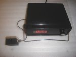
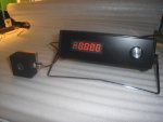
Well... we finally finished the modifications and testing of our new DIY
10 Watt Thermopile Laser Power Meter...
I will use the 1st 2 Posts for posting build pictures and additional
information rather than have them all over the Thread and hard to find.
Now I know most of the members here have been waiting for a Lamborghini
for $1000.00.... and as I've said before.. we all know that won't happen.
The Project is for anyone that has a basic knowledge of electronics and
experience in building Electronic projects from Schematics and Drawings.
I will not give a course on Electronic Assembly.
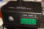
That individual must already own a Standard Kenometer or can get a hold
of one in the Future similar to the one shown in Pic #1
!!! WARNING WARNING WARNING WARNING !!!
If you have a working Kenometer and don't have the appropriate building
skills or tools... I highly recommend that you do NOT attempt this build.
You may end up with a Non Functioning Kenometer...
!!! Do so at your own risk !!!
We will not be held responsible if you ruin your Kenometer and we DO NOT
guarantee that your build will function properly...
You will also need access to a calibrated LPM to re-calibrate your Kenometer.
!!! WARNING WARNING WARNING WARNING !!!
Fig-1 = STANDARD KENOMETER
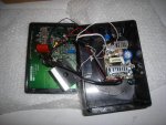
Fig-1a = Inside KENOMETER
We have taken one of our 2 Watt Standard Kenometer and have modified
it to now allow us to measure a Laser at a maximum reading (as tested) of
just over 11 Watts.. That limitation is due to the Coherent Head and the
Coherent circuit board Op Amp configuration.
While testing the Kenometer we found that the Temperature of the inside
of the supplied Radio Shack Box gets quite hot due to the Switching
Power Supply.. The temperature in the box g0t has high as 38.5 Deg. C on
one test (101.3 Deg. F).
We found that a bit too high to have the Thermopile head in that same
enclosed
space..
We opted to keep the Thermopile on the outside of the Enclosure we chose...
We decided to strip all the wiring off the Coherent Op Amp PCB and rewire it
with proper type and gauge wire.. (We found coaxial headphone cable being
used to supply power to the PCB).
Once we had built the new DIY-10W-LPM we proceeded to Calibrate it against
our Shop Newport 1825-C with Thermopile Head...
We could not get the calibration adjustment low enough... the Display was
reading a bit too high even at the lowest trim-pot setting...
We then took our other 2 Standard Kenometers and found the same slightly
over calibration and again could not reduce the value..
After tracing the circuit and values of components and modifying the PCB parts
used.. we were able to adjust the DIY-10W-LPM to the calibration Values required.
We also found that the Zero Adjust pot was a little sensitive and decided to
throw in a NOS 16 Turn 1Meg pot to make Zeroing the LPM more precise and
easier...
The Parts list denotes a 1 Turn Pot... You will need to hunt down a multi-turn pot
if you want one..
!!! WARNING WARNING WARNING WARNING !!!
If you have a working Kenometer and don't have the appropriate building
skills or tools... I highly recommend that you do NOT attempt this build.
You may end up with a Non Functioning Kenometer...
!!! Do so at your own risk !!!
We will not be held responsible if you ruin your Kenometer and we DO NOT
guarantee that your build will function properly...
You will also need access to a calibrated LPM to re-calibrate your Kenometer.
!!! WARNING WARNING WARNING WARNING !!!
So lets start with the project....
BTW... you are not locked in to using this Enclosure... you can use
any enclosure that allows the mounting of all the parts without the
Thermopile...
Here is a Parts List with suppliers and some prices at the time...
Of course you can get your parts anywhere you want as long as the specs
are respected...
1 Hammond Enclosure------------- DigiKey #HM165-ND--------- $19.88
1 Hammond Tilt Handle------------ Digikey #HM256-ND--------- $13.58
1 R14 2K2 1% 1/4W Resistor----- Digikey #P2.20KCACT-ND---- $ 1.71
2 Zero Pot 560K 1/4W Resistors- DigiKey #P560KBACT-ND----- $ 0.78
1 1Meg Zeroing Pot (1 Turn)----- eBay #130338517689-------- $ 0.75
1 Zeroing Pot Knob----------------- eBay #260526306190-------- $ 0.68
1 4-1/2 digit Voltmeter (20V)------eBay #280476426567-------- $16.38
Misc. Mounting screws Local hardware store \
6-8 feet 18 Ga. stranded wire Local hardware store --> Aprox.$10.00
1 can Flat Black Paint Local hardware store /
1 working Kenometer originally from Kenom Between $100.00-$250.00
Start...
The first thing to do is carefully take your Kenometer apart... be careful
when unsoldering the wire connections on the PCB to not damage any
printed traces...
Once you have removed the Toggle Switch... AC Connector and 1 Turn
1Meg Zero Pot.. unsolder all the Wires from the Toggle Switch... AC
Connector and the Switching Power Supply.
Unsolder all the wires connected to the PCB we will be replacing those with
new wire.
Now you can remove the Toggle Switch and AC Connector.
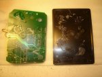
Fig-1b = Glue to Remove
You will also need to carefully remove any parts that are Hot Glued into
the Box... such as the Switching Power Supply and the Main PCB..
Very gently wiggle a flat stiff plastic tool to un-stick the parts...
If you are having a real difficult time... you might be able to heat the rear
of the PCB through the black Plastic with a Hair Dryer or other similar heat
source.
We were able to remove 2 of our Kenometer PCBs just by slowly working
around the perimeter of the PCB...
With the PCB removed carefully peel off the remaining Hot glue on the bottom
of the PCB.
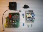
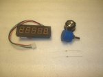
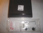
Once you are done you should have the parts shown in Fig-2
Fig-2 = Parts Removed
Fig-2a = Parts Required
Preparing the PCB....
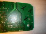
The Kenometer PCB is too big to fit correctly into the new enclosure..
you will need to cut it carefully at the Black lines as shown in Fig-3.
You will also need to make a cutout for the enclosure's mounting post.
(if your enclosure is large enough.. you may not need top trim the PCB)
Fig-3= Cut Lines
Preparing Enclosure...
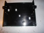
You will need to prepare the New Enclosure by gluing some plastic spacers
to help support the trimmed PCB and Switching Power Supply. We used Plastic
Model cement. We have also used Methylene Chloride with go results.
While those spacers dry... you can layout the holes you will need to cut
into the enclosure's aluminum Face Plate and Rear Panel as shown on Fig-5
and Fig-7.
Fig-5 = Face Plate hole dimensions
Fig-7 = Rear Plate hole dimensions
The Face Plate was thoroughly cleaned and painted Flat Black...then let dry
overnight.
PCB Modifications
You will need to unsolder the 10 turn 10K trim pot attached across R15 on
the PCB... Then remove R15 completely...
Also Remove R14 and replace it with the 2K2 1% resistor in the parts list..
Now re-solder the 10 turn 10K trim pot where R15 was (See Note)...
NOTE:-
We extended this 10k Calibration Pot so that we could get to the adjustment
screw later... the way it is originally installed will not allow you to do so.
You will need to change the existing resistors connected to the ends of the
1Meg Zeroing Pot for the 560K resistors in the parts list.
Be very careful to not break any PCB Traces or create solder or short circuits
by error...
Mounting/Assembly....
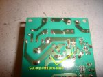
Fig-6 = Power Supply pin trim
Mount the trimmed PCB to the bottom of enclosure as shown...
Before you mount the Switching Power Supply... take a pair of flush cut
wire cutters and trim some of the longer part leads that may bend over and
create shorts as had happened to one of our power supplies.
Add 2 wires on the 120VAC side and 3 wires for the low voltage side of the
PS.
Next mount all the other parts to the Face Plate and Rear Plate if you haven't
yet done so.
Wiring....
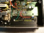
Fig-7 = Drawing/Schematic of where to connect all the parts.
Fig-8 = the parts to remove and add for the Calibration Circuit.
Fig-9 = inside wiring
Mechanically install all the parts into the Enclosure... Faceplate and Rear
Panel...
Following the Drawing/Schematic and Pictures.. wire up the parts to their
associated connection points.. be careful to connect exactly to the PCB
pads/prints shown...
Connect the Switching Power Supply's input to the AC Connector and Toggle
Switch as shown. Use heat shrink when ever possible especially on the 120V
connections.
Connect the 1 turn (or multi-turn) Zeroing Pot to the connections shown on
the Drawings.
Thermopile Head
Connect the Thermopile's shielded cable to the connector on the PCB and
cut a notch on the left side of the enclosure to pass that cable when the
cover is on.
Connect the Thermopile to the other end of that shielded cable's BNC
connector.
Re-Check all your connections that they match the Drawings/Schematics
and Pics.. Make sure there are no solder bridges and all your solder joints
are shinny and clean. (no cold joints please).
Put heat shrink or tape on all exposed connections..
Use Ty-Wraps to make a nice clean professional looking job so you will be
proud to show off your efforts..
Re-check all your wiring...
Be careful... there is 120VAC potential on the Switching Power Supply..
If you have checked all that.. then connect the power cable to the AC
connector and flick the toggle switch to ON...
There will be a slight delay for the MCU on the LED Display to boot up..
then it will light up...
IF THERE IS NO DISPLAY... DISCONNECT YOUR LPM FROM THE MAINS
AND FIND WHAT'S WRONG BEFORE YOU CONTINUE..
There is a fuse on the Switching Power Supply... check that first.. then
check your wiring and connection quality.
If I've missed something in the instructions... Just PM me and it will be
updated..
The next step in the project will be a PC Data Logging Interface...
To be continued..............
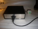
Fig-10 = Rear of DIY-10W-LPM
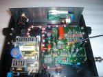
Fig-11 = Top of DIY-10W-LPM
Fig-12 = Front of DIY-10W-LPM
We noticed that the attachment Schematics and Mechanical drawings did
not print out very well...so we put Fig-4... Fig-5 and Fig-7 on our website
for download... Just print them out to see them better.
I apologize for the poor scan quality...
Download here...
Fig-4s
http://www.bauer-electronics.com/images/prodpics/Fig.%204-s.jpg
Fig-5s
http://www.bauer-electronics.com/images/prodpics/Fig.%205-s.jpg
Fig-7s
http://www.bauer-electronics.com/images/prodpics/Fig.%207-s.jpg
Jerry
You can contact us at any time on our Website: J.BAUER Electronics
Warning....PICTURE HEAVY THREAD

Well... we finally finished the modifications and testing of our new DIY
10 Watt Thermopile Laser Power Meter...
I will use the 1st 2 Posts for posting build pictures and additional
information rather than have them all over the Thread and hard to find.
Now I know most of the members here have been waiting for a Lamborghini
for $1000.00.... and as I've said before.. we all know that won't happen.
The Project is for anyone that has a basic knowledge of electronics and
experience in building Electronic projects from Schematics and Drawings.
I will not give a course on Electronic Assembly.
That individual must already own a Standard Kenometer or can get a hold
of one in the Future similar to the one shown in Pic #1
!!! WARNING WARNING WARNING WARNING !!!
If you have a working Kenometer and don't have the appropriate building
skills or tools... I highly recommend that you do NOT attempt this build.
You may end up with a Non Functioning Kenometer...
!!! Do so at your own risk !!!
We will not be held responsible if you ruin your Kenometer and we DO NOT
guarantee that your build will function properly...
You will also need access to a calibrated LPM to re-calibrate your Kenometer.
!!! WARNING WARNING WARNING WARNING !!!
Fig-1 = STANDARD KENOMETER
Fig-1a = Inside KENOMETER
We have taken one of our 2 Watt Standard Kenometer and have modified
it to now allow us to measure a Laser at a maximum reading (as tested) of
just over 11 Watts.. That limitation is due to the Coherent Head and the
Coherent circuit board Op Amp configuration.
While testing the Kenometer we found that the Temperature of the inside
of the supplied Radio Shack Box gets quite hot due to the Switching
Power Supply.. The temperature in the box g0t has high as 38.5 Deg. C on
one test (101.3 Deg. F).
We found that a bit too high to have the Thermopile head in that same
enclosed
space..
We opted to keep the Thermopile on the outside of the Enclosure we chose...
We decided to strip all the wiring off the Coherent Op Amp PCB and rewire it
with proper type and gauge wire.. (We found coaxial headphone cable being
used to supply power to the PCB).
Once we had built the new DIY-10W-LPM we proceeded to Calibrate it against
our Shop Newport 1825-C with Thermopile Head...
We could not get the calibration adjustment low enough... the Display was
reading a bit too high even at the lowest trim-pot setting...
We then took our other 2 Standard Kenometers and found the same slightly
over calibration and again could not reduce the value..
After tracing the circuit and values of components and modifying the PCB parts
used.. we were able to adjust the DIY-10W-LPM to the calibration Values required.
We also found that the Zero Adjust pot was a little sensitive and decided to
throw in a NOS 16 Turn 1Meg pot to make Zeroing the LPM more precise and
easier...
The Parts list denotes a 1 Turn Pot... You will need to hunt down a multi-turn pot
if you want one..
!!! WARNING WARNING WARNING WARNING !!!
If you have a working Kenometer and don't have the appropriate building
skills or tools... I highly recommend that you do NOT attempt this build.
You may end up with a Non Functioning Kenometer...
!!! Do so at your own risk !!!
We will not be held responsible if you ruin your Kenometer and we DO NOT
guarantee that your build will function properly...
You will also need access to a calibrated LPM to re-calibrate your Kenometer.
!!! WARNING WARNING WARNING WARNING !!!
So lets start with the project....
BTW... you are not locked in to using this Enclosure... you can use
any enclosure that allows the mounting of all the parts without the
Thermopile...
Here is a Parts List with suppliers and some prices at the time...
Of course you can get your parts anywhere you want as long as the specs
are respected...
1 Hammond Enclosure------------- DigiKey #HM165-ND--------- $19.88
1 Hammond Tilt Handle------------ Digikey #HM256-ND--------- $13.58
1 R14 2K2 1% 1/4W Resistor----- Digikey #P2.20KCACT-ND---- $ 1.71
2 Zero Pot 560K 1/4W Resistors- DigiKey #P560KBACT-ND----- $ 0.78
1 1Meg Zeroing Pot (1 Turn)----- eBay #130338517689-------- $ 0.75
1 Zeroing Pot Knob----------------- eBay #260526306190-------- $ 0.68
1 4-1/2 digit Voltmeter (20V)------eBay #280476426567-------- $16.38
Misc. Mounting screws Local hardware store \
6-8 feet 18 Ga. stranded wire Local hardware store --> Aprox.$10.00
1 can Flat Black Paint Local hardware store /
1 working Kenometer originally from Kenom Between $100.00-$250.00
Start...
The first thing to do is carefully take your Kenometer apart... be careful
when unsoldering the wire connections on the PCB to not damage any
printed traces...
Once you have removed the Toggle Switch... AC Connector and 1 Turn
1Meg Zero Pot.. unsolder all the Wires from the Toggle Switch... AC
Connector and the Switching Power Supply.
Unsolder all the wires connected to the PCB we will be replacing those with
new wire.
Now you can remove the Toggle Switch and AC Connector.
Fig-1b = Glue to Remove
You will also need to carefully remove any parts that are Hot Glued into
the Box... such as the Switching Power Supply and the Main PCB..
Very gently wiggle a flat stiff plastic tool to un-stick the parts...
If you are having a real difficult time... you might be able to heat the rear
of the PCB through the black Plastic with a Hair Dryer or other similar heat
source.
We were able to remove 2 of our Kenometer PCBs just by slowly working
around the perimeter of the PCB...
With the PCB removed carefully peel off the remaining Hot glue on the bottom
of the PCB.
Once you are done you should have the parts shown in Fig-2
Fig-2 = Parts Removed
Fig-2a = Parts Required
Preparing the PCB....
The Kenometer PCB is too big to fit correctly into the new enclosure..
you will need to cut it carefully at the Black lines as shown in Fig-3.
You will also need to make a cutout for the enclosure's mounting post.
(if your enclosure is large enough.. you may not need top trim the PCB)
Fig-3= Cut Lines
Preparing Enclosure...
You will need to prepare the New Enclosure by gluing some plastic spacers
to help support the trimmed PCB and Switching Power Supply. We used Plastic
Model cement. We have also used Methylene Chloride with go results.
While those spacers dry... you can layout the holes you will need to cut
into the enclosure's aluminum Face Plate and Rear Panel as shown on Fig-5
and Fig-7.
Fig-5 = Face Plate hole dimensions
Fig-7 = Rear Plate hole dimensions
The Face Plate was thoroughly cleaned and painted Flat Black...then let dry
overnight.
PCB Modifications
You will need to unsolder the 10 turn 10K trim pot attached across R15 on
the PCB... Then remove R15 completely...
Also Remove R14 and replace it with the 2K2 1% resistor in the parts list..
Now re-solder the 10 turn 10K trim pot where R15 was (See Note)...
NOTE:-
We extended this 10k Calibration Pot so that we could get to the adjustment
screw later... the way it is originally installed will not allow you to do so.
You will need to change the existing resistors connected to the ends of the
1Meg Zeroing Pot for the 560K resistors in the parts list.
Be very careful to not break any PCB Traces or create solder or short circuits
by error...
Mounting/Assembly....
Fig-6 = Power Supply pin trim
Mount the trimmed PCB to the bottom of enclosure as shown...
Before you mount the Switching Power Supply... take a pair of flush cut
wire cutters and trim some of the longer part leads that may bend over and
create shorts as had happened to one of our power supplies.
Add 2 wires on the 120VAC side and 3 wires for the low voltage side of the
PS.
Next mount all the other parts to the Face Plate and Rear Plate if you haven't
yet done so.
Wiring....
Fig-7 = Drawing/Schematic of where to connect all the parts.
Fig-8 = the parts to remove and add for the Calibration Circuit.
Fig-9 = inside wiring
Mechanically install all the parts into the Enclosure... Faceplate and Rear
Panel...
Following the Drawing/Schematic and Pictures.. wire up the parts to their
associated connection points.. be careful to connect exactly to the PCB
pads/prints shown...
Connect the Switching Power Supply's input to the AC Connector and Toggle
Switch as shown. Use heat shrink when ever possible especially on the 120V
connections.
Connect the 1 turn (or multi-turn) Zeroing Pot to the connections shown on
the Drawings.
Thermopile Head
Connect the Thermopile's shielded cable to the connector on the PCB and
cut a notch on the left side of the enclosure to pass that cable when the
cover is on.
Connect the Thermopile to the other end of that shielded cable's BNC
connector.
Re-Check all your connections that they match the Drawings/Schematics
and Pics.. Make sure there are no solder bridges and all your solder joints
are shinny and clean. (no cold joints please).
Put heat shrink or tape on all exposed connections..
Use Ty-Wraps to make a nice clean professional looking job so you will be
proud to show off your efforts..
Re-check all your wiring...
Be careful... there is 120VAC potential on the Switching Power Supply..
If you have checked all that.. then connect the power cable to the AC
connector and flick the toggle switch to ON...
There will be a slight delay for the MCU on the LED Display to boot up..
then it will light up...
IF THERE IS NO DISPLAY... DISCONNECT YOUR LPM FROM THE MAINS
AND FIND WHAT'S WRONG BEFORE YOU CONTINUE..
There is a fuse on the Switching Power Supply... check that first.. then
check your wiring and connection quality.
If I've missed something in the instructions... Just PM me and it will be
updated..
The next step in the project will be a PC Data Logging Interface...
To be continued..............
Fig-10 = Rear of DIY-10W-LPM
Fig-11 = Top of DIY-10W-LPM
Fig-12 = Front of DIY-10W-LPM
We noticed that the attachment Schematics and Mechanical drawings did
not print out very well...so we put Fig-4... Fig-5 and Fig-7 on our website
for download... Just print them out to see them better.
I apologize for the poor scan quality...
Download here...
Fig-4s
http://www.bauer-electronics.com/images/prodpics/Fig.%204-s.jpg
Fig-5s
http://www.bauer-electronics.com/images/prodpics/Fig.%205-s.jpg
Fig-7s
http://www.bauer-electronics.com/images/prodpics/Fig.%207-s.jpg
Jerry
You can contact us at any time on our Website: J.BAUER Electronics
Attachments
Last edited:


