Welcome to Laser Pointer Forums - discuss green laser pointers, blue laser pointers, and all types of lasers

Buy Site Supporter Role (remove some ads) | LPF Donations

Links below open in new window

FrozenGate by Avery

Direct connect heat sink

I think the biggest headache I've run into with these type hosts is there's no direct connection from the driver to the battery so like in the dorcy jr setup you have to solder the driver to the remaining board at the top of the battery (what used to be the original led driver) then from there to the diode. It leaves a wire trail from the bottom to the head and as such must make the heatsink diode assembly remain stable while you twist the head back onto the battery section.

Now the way I did mine in the dorcy Jr. host was to still utilize the spring and plastic holder to make contact with the old driver and transfer the juice to the flexdrive. It allows for removing the head without damaging the driver components or wires. But, it's been my experience that it is VERY easy to twist the head off and twist the wires as well thereby shearing off the diode pins.


daguin said:
Why would a pin-to-wire connection be any more vulnerable to degradation than a pin-to-solder pad connection?
especially if the wire is super-flexible...
good stuff! that's silver plated copper, solders easily.
one caveat: use a good sharp wire-stripper.
 
Kenom said:
I think the biggest headache I've run into with these type hosts is there's no direct connection from the driver to the battery so like in the dorcy jr setup you have to solder the driver to the remaining board at the top of the battery (what used to be the original led driver) then from there to the diode.  It leaves a wire trail from the bottom to the head and as such must make the heatsink diode assembly remain stable while you twist the head back onto the battery section.

Now the way I did mine in the dorcy Jr. host was to still utilize the spring and plastic holder to make contact with the old driver and transfer the juice to the flexdrive.  It allows for removing the head without damaging the driver components or wires.  But, it's been my experience that it is VERY easy to twist the head off and twist the wires as well thereby shearing off the diode pins.


You appear to be referring to opening and/or closing a laser incorrectly. This does indeed happen, but so does people "cleaning" the diode window with glass cleaner ;) If the laser is opened or closed incorrectly, or if it is built poorly is a different problem from "stress, spurious wire twisting and/or degradation of solder joints.

Peace,
dave
 
Kenom - I've been thinking about that problem. Since the head-to-body twist connection is not done very often (battery replacement happens at the other end), maybe a gold-plated pin-and-socket at the precise center could do the job well? A whole bunch of such pins/sockets can be had really cheaply if the right nn-pinned male and female connector is cannibalized (or the pin sets can be bought outright). What do you folks think?
 
daguin said:
[quote author=hevnsnt link=1230512410/20#29 date=1230525554]
I actually disagree,
I think IN EVERY BUILD it makes the most sense to have the driver directly connected to the diode (if possible)
Of course it is of course not possible to have the driver directly connected in every build, and sometimes you will be forced to use wires.  Wires will put additional stress on the pins, have the possibility of becoming twisted, and the joints could degrade over time.
That being said I didnt come in here offering any solutions  ;)


If a laser is built correctly, there is no movement of the components to add any stress to the pins or to allow any "twisting" of the wires.  Why would a pin-to-wire connection be any more vulnerable to degradation than a pin-to-solder pad connection?

Peace,
dave[/quote]

While I don't necessarily disagree with any of your counter points, the fact is that wires are always 2nd place to direct connection. By design they lend themselves to movement, and therefore are a weaker solution.

Why dont we all just wire-wrap our drivers instead of using printed circuit boards?

I am not saying that using wires to bridge the connection between the diode & driver should be avoided, hell I have two hosts right in front of me in that configuration. As you said, if done correctly, it can be a completely stable solution.

But what I would like to see out of this is a well thought-out, engineered solution. I think you guys are off to a great start.
 
hevnsnt said:
Why dont we all just wire-wrap our drivers instead of using printed circuit boards?
well... in the spirit of full discussion:
if that wirewrap were done well, and then soldered, it would be far more stable than many of the home-made self-soldered pc boards I've seen. We are talking soldered connections to the diode, ya know ;-)
 
danq said:
What I'd really like to see is a screw-down mount for the diode (much better than a screw-up mount), rather than a press-fit. IMO with close tolerance and a film of heatsink grease, near-perfect thermal transfer can be combined with diode replaceability.  That would also accomplish easier installation and much smaller chance of ruining a diode in the pressing.!

I agree. Screwing something up is less fun than screwing it down. ;)

The ultimate realization of that approach, IMO, is this part:

• Function: Threaded diode clamp.
• External dimensions: 10.0mm(Ø) × 3.0mm(L).
• Opening dimension: 4.0mm(Ø)
• Recess dimensions: 5.7mm(Ø) × 1.5mm(H)
• Recess chamfer: 0.5mm.
• Diode locking: Index mark.
• Material: Copper-tungsten alloy.
• Coating: Gold electroplated.
• Front milling: spanner groove, aligned with index mark.

The electroplating is reasonably easy to do, and insures metal-to-metal thermal contact. When the diode is pressed into the clamp, the gold is soft enough that it molds itself to the diode baseplate, giving excellent thermal transfer characteristics. It also makes the material extremely corrosion resistant, and has a very nice finish. Additionally, it makes the threads lock tight, since the soft material fills out any deviations in the grooves. The main benefit is the tight thermal coupling, though.

I realize 10mm may not be the same diameter as the lenses folks are using, so it could be changed. Either way, all you really need is a hole with matching threads, in any body or heatsink, and then you're set. The diode wires can be attached before you screw it in. Actually, it would be best if there's a small ridge on the bottom of the hole to press the diode into the host, obviating the need for a seperate tool to do that. If you want to add fancy options, it shouldn't be too tricky to make a threaded piece that can take a Nd:YVO+KTP crystal, one you can just screw in on top of a 808nm and then add the lens after that.

Of course, such a thing would essentially be a cheaper (one hopes) and better version of the optic tubes offered by Thorlabs.

If it is made, I'll want a few, with a simple 50x50mm plate and four M4 screw holes to mate them to a TEC. :D

A mere heatsink, however, is something I have little use for... I have a drill press.
 
hmmm... I don't quite have that visualized - could you draw it?

and how 'bout just copper instead of that alloy? easier to work, so might cut cost dramatically.

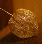
the plating is easy - I've done gold over copper with nickle as intermediary, but don't know if the nickle would be needed here (it was for strength and gloss - see below)
 

Attachments

  • gold_tomatillo_001.jpg
    gold_tomatillo_001.jpg
    59.5 KB · Views: 84
Nice!

Copper works if it's gold plated to avoid corrosion.

And, yeah, I guess the CuW would wear out the bits pretty quickly, and the scrap isn't easy to melt. Got to love the hefty feel and the thermal expansion coefficient, though. Really, plated copper or aluminum should be fine, and would probably have far wider appeal.

As for drawings, gimme a minute and I'll make a quick sketch.

Edit: Suddenly got busy. Will get back to you tomorrow.
 
*********** This thread has been updated **********************
Reread the first post in this thread, changes have been made to the previous versions, this should be more to you're liking.  8-)
                    Catmandoo
 
I'll repost my comments here for this audience

I really like the design. Unfortunately, I rarely build anything with these hosts anymore. Part of the "lure" of the hobby for me is the creativity needed in making new and different hosts "work."

As far as price is concerned, you are going up against the Jayrob and the Dark_Horse heat sinks. Those run less than $25 each (with shipping). I absolutely agree that this is a better design. Unfortunately, the people that use these "stock" hosts the most are NOOB's. NOOB's generally look for the lowest price, NOT the best components.

I will probably get one to use in experimental work, but that will be it.

Peace,
dave
 
         Daniel has updated the design and has new drawings in the first post of this thread.

                                This is an update as of December 12, 2008
                                          updating the last update

Check it out and give you're input. The input from you all has gotten this alot closer to the launch pad, what else before lift off ?

What host's would you like to see this made for ?
Tutorials aside, which host's do you really use or would like to if you had a heat sink for it ?

8-)  CMD
 
i set my diodes in the module with a washer i found not too long back, the hole in the center is just big enough for the pins to fit through then then i can grasp onto the washer and press te diode into the module.....works great for me, and it cost me 4 cents from the hardware store.
 
re: Dave's comment about hosts used.

Perhaps - if you'll be making these yourself - you could tool up to do all of the construction standard, except for some few external dimensions; then just modify those few specs to fit particular hosts? For example: maybe only the hs's outer diameter, face diameter, and the length may be all that separate most hosts? or maybe there are some number of hosts that could be fit by varying only those 3 dimensions.
:-?
DanQ
 
You are correct danq,
This will be an easily adapted heat sink, but lets not get ahead of ourselves, start out with a couple of the most popular host's. Once that ball is rolling and everything is working, then expand the scope . I see special orders being a very accomplishable in the future, Dan loves a good challenge !


Back
Top