Welcome to Laser Pointer Forums - discuss green laser pointers, blue laser pointers, and all types of lasers

Buy Site Supporter Role (remove some ads) | LPF Donations

Links below open in new window

FrozenGate by Avery

Connecting A laser Diode/Driver to a 7805 Voltage Regulator

I completely understand and by no means am i trying to disrespect any of your advice or knowledge. I am simply trying to understand, The Qzar system originally had Green and Red lasers, red lasers in the red and green lasers in the green.

If you look it up on the internet there isn't even a repair manual. I am responsible for keeping all the equipment working. I would just like to see green lasers in the green vests/guns, not red ones. I have a repair manual but it is not genuine.. just a troubleshooting manual which shows you what to do. Just by looking at parts you can see if parts are broken or need to be re-soldered (repair manual is useless).

I do not fully understand the difference between red/green lasers but I do understand that they are different. That's why I am coming to you guys. I have no doubt that the voltages for the lasers will be correct. The guns were designed to be compatible with them, There is a simple "dip switch" on them that controls weather the gun is red or green. The motherboard controls everything on the pack/gun pulling the trigger simply triggers the laser each time a shot is fired.

What I can tell you is that, When i opened one of the laser casing's the Diode had 3 pins which was already connected to a Driver. (all lasers had a driver attached) The driver had a red and black wire connected to the PCB. There was no spring and the Driver looked nothing like what you see when you open up a standard laser pointer. If a green Diode looks the same as a Red one then I thought switching them would be easy. This may not be the case, I appreciate all of your help and im trying to absorb all this.

The instructions I Received showed me a whole piece with the Diode, Driver and Spring. It Explained how to connect the Voltage regulator to the whole piece and then said it would work. I figure that connecting a green Diode, or "whole piece" would have the same effect.

Here comes the tricky part. There are 5 revisions of the same gun board. They all work the same, just changes in design. What i did notice is that there seems to be a stand alone battery pack for green lasers ( another spot within the gun mold ) What it looks like is that for green lasers, the green laser was connected to another battery then to the PCB. I will use a multimeter and figure out what the voltages/current are through the standard laser connections. All lasers were pre-assembled (obviously) its the Diode connected to the driver then the PCB. All guns have red lasers so the external battery has been removed.


I think pictures are in order here - show us what the setups look like (open).
 
There really isn't much to show. I'll take pictures with my phone but they wont be uploaded till late Wednesday night. Ill try and give as much info as I can, I really appreciate all the help you guys are willing to give. I am truly grateful. All you will basically see is the Gun board, laser tube and a laser connection to the PCB.
 
There really isn't much to show. I'll take pictures with my phone but they wont be uploaded till late Wednesday night. Ill try and give as much info as I can, I really appreciate all the help you guys are willing to give. I am truly grateful. All you will basically see is the Gun board, laser tube and a laser connection to the PCB.

That could really help :)
 
It could help but All i can show you is a modified laser casing. ( laser diode and driver cant be exposed ) If i comprise a working laser I can.. otherwise I don't have to tools to undo the casings around the current red lasers in place. Almost like they were built to not be taken apart. I'll see what I can do as im sure it will help.

A red laser cost 250 from manufacturer and a green one cost 300-450. Ridiculously high for no reason. A pack brand new cost anywhere from 1500-1800 depending on which color (red or green, depends on laser). the packs are not manufactured anywhere its just left over stock that a company bought that sells for profit. Im going to bed now but ill be back tomorrow or in 12 hours :-)

Thank you for your help i really appreciate it.
 
The green lasers came in today but it was a class 3 and didn't look safe. It was a high powered astronomy laser. I can get the specs on the laser if needed but do you know of any safe lasers that would be safe? There is no long term exposure it only goes flashes for a second when the trigger is pulled.

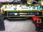
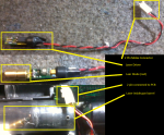
Here are a couple pictures.
 

Attachments

  • Photo0222.jpg
    Photo0222.jpg
    142.8 KB · Views: 867
A photo of the original Laser that goes in that gun is what we need.
 
your looking at it. Its just a diode with 3 pins, that connect to the little driver. I had to make a new shell for it to give it size to fin in the gun barrel after ripping apart the old one.
 
Sorry I had to re-size it. didn't know it wasn't accepted.
 

Attachments

  • laser pictures.png
    laser pictures.png
    554.8 KB · Views: 2,416
So your going to hook up the power that went to the red laser to the 5v regulator?
Because for a 5v regulator to work, you need atleast 6 V on the input pin, and most likely the red laser would have ran on less than that,

Also you could solder a wire between the pins on that push button switch, it would probably work better.

Where would i put the red/black wire if i dont use a regulator?
 
Where would i put the red/black wire if i dont use a regulator?

What you need to do, is what I suggested back in post 11.

You need to measure the current and voltage that would normally be going from that main PCB to the laser. Until we know those pieces of information, I don't see any way that we can actually provide you with real advice.

This forum is generally happy to help people with interesting projects like this, but you've got to be willing to do the testing that we can't, since we don't have this thing in front of us.
 
Last edited:
I measured the current and voltage yesterday but I forgot to bring the paper home with me. When the gun was energized it was getting a reading of like 0.58 I believe, When it was De-energized it has 7.8v. Ill check again and post back.

As far as hooking up a red laser pointer though, just a standard laser pen. You guys think there is no need for a regulator? So where would i put the red and black wire on the driver? Black wire to the spring then red to the +ve on the driver?
 
I measured the current and voltage yesterday but I forgot to bring the paper home with me. When the gun was energized it was getting a reading of like 0.58 I believe, When it was De-energized it has 7.8v. Ill check again and post back.

HUH? There was voltage across the driver when the laser wasn't outputting anything?

And what was "0.58"? The current? When the laser was on?

As far as hooking up a red laser pointer though, just a standard laser pen. You guys think there is no need for a regulator? So where would i put the red and black wire on the driver? Black wire to the spring then red to the +ve on the driver?

You keep trying to jump three steps forward. This isn't like a hollywood "bomb scene" where there's a universal principal that you "always cut the green wire". You need to give us data first. Nobody is going to tell you how to hook up wires on a system that you haven't provided us with enough info about yet. If you can clarify the current and voltage going to the stock red laser when it's firing, I can probably give you the answer you're looking for.
 
Last edited:
Yes there was voltage across the driver when the laser wasn't outputting anything. I will double check and give you readings im not trying to jump ahead. No it was not current it was all voltages. I got a reading of 7.8v when the gun was not ready for play and 0.58v when it was. Pulling the trigger had no effect. I will measure current as well if needed.

You have been answering and helping me with all my questions im sorry I feel a little rushed. not trying to rush or frustrate you as well :-/

This was my first question. How do I hook up a standard laserpen to a 7805 voltage regulator. I was told this would work as another company has used this technique with the same laser system.

I posted the picture below you and you said it looked correct. However another person posted that I would not need a voltage regulator. Do you know where i would put the +ve and -Ve connections to this ?

This question is where it all started. Getting into green lasers is different but once i get this to work I can move on to green.

For this pictures sake, all voltages/currents are correct. the gun already controls all of that, I just need to know how to hook it up. I just want to make sure the wiring is correct before I hook it up.
 

Attachments

  • newlaser.png
    newlaser.png
    141.1 KB · Views: 10,587
Last edited:
Honestly, I'm not sure why an LM7805 would have been suggested. I don't know of any pointers or modules that like 5V of input (green or otherwise).

I could see using an LM317 3.3V, but not an LM7805.

Regardless though, I'm still confused by these measurements, and would want to understand them better before suggesting anything. For one, why on earth would the red laser driver be dropping voltage (7.8V no less!) when it's not outputting any laser light?
 
Last edited:
I could have messed up when taking readings yesterday but I will double check. I don't fully understand the workings of the PCB or the lasers. Packs were manufactured in the 90's and discontinued. I don't know how the voltages are dropped or amplified throughout the gun before reaching the laser's connection. There is so much the board controls, Its everything. The display card can shut the board down, the front vest can cause problems with the gun board and vise versa.

I will try and get more/accurate readings and Ill do my best to explain them. One thing I do know is that another Q-zar center is making there own lasers as described above and apparently it works.

Thats why I wanted to know how to hook it up to the 7805, but the pictures that I showed you of the gun and laser that was put in the gun is connected straight from the driver.


Back
Top