

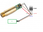
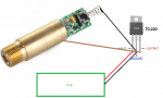
This may be a little hard to explain but lets say that I have the Diode/Driver already. I need to connect this to a 7805 Voltage Regulator. Then have a +/- wire connect to a PCB via 2 pin molex connector.
The picture im attaching are instructions that were given to me and written poorly. Im sure that this diagram is not correct. Can you guys help me out?
The picture im attaching are instructions that were given to me and written poorly. Im sure that this diagram is not correct. Can you guys help me out?


")
