Welcome to Laser Pointer Forums - discuss green laser pointers, blue laser pointers, and all types of lasers

Buy Site Supporter Role (remove some ads) | LPF Donations

Links below open in new window

FrozenGate by Avery

Building a orange (613nm) Laser from scratch with off-the-shelf parts (and for cheap!)

Hello Guys!

I now have a better estimate.

If we talk low cost, i can offer:
730€ with the 638nm 185mW SM diode, this module should reach 618nm. This would only be the module, without any driver.
If we talk the best module, ready to use, fully fledged we are at 1020€ including driver and the better 633nm 100mW laser diode. It should reach 613nm.
The module will use around 70W at 24V (around 3A).
Please keeping mind, every diode is different, so i cannot guarantee the actual wavelength.

If you want to get an even lower wavelength, we could stack a tec underneath the complete module. I didnt calculate a price and the power usage would be enormous (like >300W) and you could get to around 610nm.

Drop me a PM or leave a comment if you are interested. If enough people are interested, we could get the price down.


Very cool that you can do this, but too rich for my blood. Sorry.

I love what you have been able to do with this though. Its incredible you can cool these to that extent. Shifting 20+ nm in wavelength and keeping the temperature there is remarkable.

I recall seeing this done with liquid Nitrogen, but obviously there was very little control on the output.
 
I am still not done Guys!
I just got my 633nm diodes.


And i updated the case to my new design. I will publish results as soon as my tecs arrive.
front.png

I will also sell my prototype if someone would be interested! It got a 700mW sharp diode in it and i need to measure the Wavelength at full power, but i assume it should be around 620-625nm. Its cheap because it does not look good, however its fully functional. A perfect base for someone who wants to thinker with cooling different diodes. Or just a module with a really low orange-red wavelength at full power.
PM me!
 
Hello Guys,

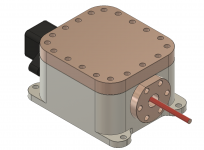
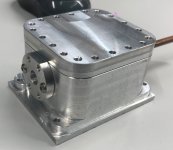
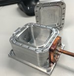
i just wanted to keep you updated. The rendering is now reality. I just have to face the bottom of the case, everything else is done!
Have a look, isn't it beautiful, just imagine the orange beam coming out of it:

IMG_0772.jpg
IMG_0774.jpg

You dont need to imagine it for long, the delivery of the tecs is scheduled for 4.10. so coming monday.
I will have to clean every part and assemble everything. I will make my first tests on monday so i will keep you updated with results.

have a nice evening
 
Nice job on protecting from humidity. I like the idea any diode you mount in that housing let's you shift the wavelength by a significant amount. How useful to be able to stimulate a sample with a single frequency LD, then shift the input frequency both directions by +-5nm and re-capture the emissions lines and map matching wavenumber shifts.
 
Sadly my tecs are late, the shipping provider did screw something up. So I got them today not on Monday.
This means I could not do tests as I am currently in the middle of assembly.
Now I need to wait until the thermal adhesive has set, this will take up to 24h. :(
As everybody can see: the end is near, but it takes a while.
I keep you updated!
 
At least you are doing something. Very easy to talk about but much harder to do.
 
At least you are doing something. Very easy to talk about but much harder to do.
Talking and not doing is for politicians :D

I misestimaed the thermal adhesive set time, for deep grooves its significantly more time than for shallow ones. So i will still take time until i can close the module and do a proper vacuum. Luckily i also had a test sample the same geometry to test the setting time, so my current time estimate is 5 days :((((
But i could not contain myself and connected the module to a vacuum pump anyway. I could not use the right seal (its a one-time-seal) because the adhesive still needs to set and therefor outgas which means i need to have the module open. This in turn results in bad vacuum and therefor thermal insulation. I used a rubber seal instead of the metal to metal seal that this module is designed for.

However i still got some results that allready impress me. I got down to 614nm. Thats one lousy nm away from my estimated 613nm and 2nm better than my last "highscore". Thats again at full output power, stabilized temperature.
I assume i get to 613nm (may _MAY_ even lower) if i have the fully cured adhesive and the module heated + better sealing material.
Wish me luck that i will get there!
But still 614nm is no joke, i am still quite satisfied with the color!
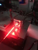
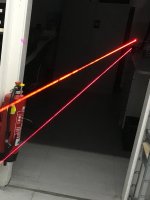
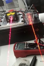
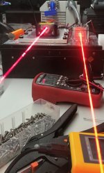
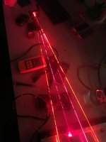
I had a little time to play around and make some beam shots. The red laser is a 660nm diode running at around 250mW, the orange is 100mW. The phone camera does make the orange a little more "red", especially if it only has the 614nm as a reference. You can see this good in the first picture. Therefore i included the 660nm in every other picture.
Have a look:

IMG_0787.jpg
IMG_0793.jpgIMG_0788.jpgIMG_0789.jpgIMG_0794.jpg
 
You may find you get a higher total deltaT by using 2 stages of TEC over 3 stages of TEC, and not get your box as hot. This is because of each series stage of junctions being a higher heat load than your diode.

You may also get your last 2nm by adding IR shielding around the LD cold platform inside to de-couple IR from the warm walls of the machined housing. IR temp coupling in my vacuum chambers always amazes me even on bright shiny metal surfaces. Multiple layers of thin metal foils over your cold platform will give you more deltaT, maybe 2nm of it.
 
... you get a higher total deltaT by using 2 stages of TEC over 3 stages ....
I already talked about this with my tec manufacturer, he already recommended to up my setup to a 5 stage tec for lower temperatures. I currently use a 4 stage element (one element that has 4 built in stages).
Your assumption is correct if you consider a fixed heatsink size (a small one), however if you are not constraint by having a bigger heatsink, you can keep the hot side at a lower temperature even if you have a increased thermal load. The TEC is specially made to reach low temperatures. The stages are made to have the right "power" to transfer the increased heat load with each stage. They use so many stages to get the temperature differential across each stage down to only a "few" degrees (30K per stage in my case), this increases the efficiency significantly. The stages are also completely different regarding the material used, each stage uses a different ingot material thats optimized for a specific hotside temperature, otherwise each stage would get a performance hit. Some materials work best at 50°C Hotside, some are better at 0°C hot side.

... adding IR shielding around the LD ..... even on bright shiny metal surfaces.
Thats very very interesting! I was planing and thinking about that in the design phase. I researched the emissivity of milled aluminum and got around 0,05, so I was thinking "good enough". In reality, both the emitting and the receiving surface (diode mount and inner casing wall) are reflective, so I assumed shielding wasn't doing anything.
Are you by any change using stainless steal containers / cold platforms? Stainless has a emissivity of around 0,5. So there it would make a huge difference but on aluminium it does not sound like it would make a difference.

A quick research did not turn up any materials that can be used for shielding and are vacuum "safe". Do you have any recommendations?

..... multiple layers of thin metal foils over your cold platform....
Do you think this has to do with IR or are you trying to reduce the mean free path length between the cold and hot elements?
I was thinking about reducing the path length by machining a cover for my diode mount, this would halve the free path length. As my path length is already larger then the casing, I assume that adding a barrier will shorten the length, thus decreasing the thermal resistance. There could also be an improvement because the shield will reduce the effective temperature difference by getting to 1/2 the temperature of the cold platform. So IR will also be reduced by having only 1/2 of the temperature.

Thanks for your input, not many people are there to help, seems like a very niche topic to talk about.
 
Farbe2, Firstly congratulations on such nice results.
I had previously started to a similar project, but at a much lower quality and much more MacGyvered. I never finished it anyway.
Have you thought about adding the external grating to tune the wavelength a bit lower?
 
... adding the external grating ...
I considered that in the development phase. I then looked at prices and changed my mind :D.
I would love to try a grating, however the price it to high. If i really want a extra few nm, i could add it external. However i think that it will not have much effect.
Take a look at the measured graph in post #55 Link
You can clearly see the "led" emission spectrum that gets out of the cavity. I assume that this somewhat correlates with the laser mediums gain bandwith. This means that the diode is already running on the lower end of its gain bandwidth, so tuning could only be possible in the "up" direction (longer wavelength). Thats only speculation on my part! However it would still be possible to make the line width narrower! (and therefore maybe 0,5nm tuning "down")
Buying a grating for >120€ just to find out is currently out of budget. D:

Next update:
Today, 90h adhesive set time have past. I checked my sample glue up and it was not fully set! That makes sense as the flat (tec to housing) surfaces make a small gap that does not allow molecules to pass easily. It also gets longer the further the adhesive sets.
My first estimate was based on 13h set time, however the set rate does slow down significantly as the gap gets longer. So i will give it another 5 days to fully cure.
Fully cured adhesive is very important! If its not set, the vacuum will get significantly worse over time! So as hard as it is, i need to keep my composure and dont experiment with the module.
 
It's definitely the IR not the mean path, my chambers can pump down below 1micronHg, and the surfaces are surface insulated.

I have a IR heat flux sensor to be able to easily quantify it. It's what lead me to multiple layers of gold foil separated by a polyethylene mesh scrim. This is because a single foil layer just becomes an equilibrium point between the two Temps. Each increasing layer buys some extra IR decoupling.

I also once believed the low emissivity would make it not a serious issue. What cancels this is the geometry of the outside hot radiation surface. In my spherical chambers I have IR coupling factor of 20:1 or so relative to the cooled test fixture. This is more than enough to balance out the low surface emissivity and become a dominant heating source.

I tested heating and cooling my 375nm diode laser yesterday. This is not a single mode diode, at least 3 output frequencies (sadly). Cooling the diode had almost no effect on the dominant 375nm wavelength, but did cause one minor mode peak to vanish. In heating and cooling a 660nm single mode red, it went up to 664nm from heating, but then suddenly the output fell off sharply at around 70degC, but fortunately returned to full output after cooling a bit. In forced cooling, it reached 651nm! And stayed single mode the whole trip down.
 
Your adhesive will set something like 1/2 the cure time for every 10-15degC hotter it's sitting at during cure. Drive a small reverse TEC current and it should setup a lot sooner.
 
.. adhesive will set something like 1/2 the cure time for every 10-15degC hotter ..
I already do that, i have engineered a high end adhesive set box. It consists of a high end cardboard box with a integrated air heating device :D

I did not check the coupling factor, but this makes sense.
I will check how i can implement the IR shielding, but i am afraid that i can't keep it in place.

How deep does your coldplatfrom cool? (And how does it function - Tec?)

as for you 660nm diode: I tested too, from 55°C to -45°C, i got the most drift out of this diode. Around 23nm from 665nm to 642nm. I tested in my prototype (and i did not wait for the good vacuum), so i only got to -45°C. Thats around 0,23nm/k for the first 100k drop. If we assume that this rate will keeps up in my finished module. I could get from 665nm to 630nm. a shift of around 34,5nm! Maybe a little more if we heat more. Thats already impressive.
I tested some other diodes but all green/blue diodes i had on hand drifted by only around 5nm (+-1nm) over the whole range. I also had a single mode 405nm Blu-ray diode that got me 7,5nm drift over my whole temperature range.

However, if you are interested, it would be easy to measure a set of diodes and use low/high ones to make a pair that has a good separation.
For example: 488nm single mode diodes, out of a lot of 50, the lowest was 485nm and the highest was 491,5. Thats already 6,5nm. If we use these two diodes and cool / heat them, the spread will get larger.
You can get the 488nm sharp laser diodes wavelength selected from 475nm-500nm for about 400$ per diode (if you order only a few and not 2k or more. This is definitely much cheaper than the cost of a high level cooling/heating assembly and can be just inserted into the usual diode mounts.

Singlemode


Back
Top