GooeyGus
0
- Joined
- Mar 8, 2008
- Messages
- 2,669
- Points
- 48
i am pretty sure drlava's driver doesn't use the pd pin. it is just constant current like all the other drivers out therewoop said:[quote author=toked323 link=1212653254/24#24 date=1212807549]I think why drlava's is good is because he had to solder on the PD leg on a diode to the driver for feed back through the IC i think it cuts it off? Best i think is to incorporate the PD leg into a design for feedback
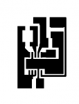
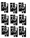
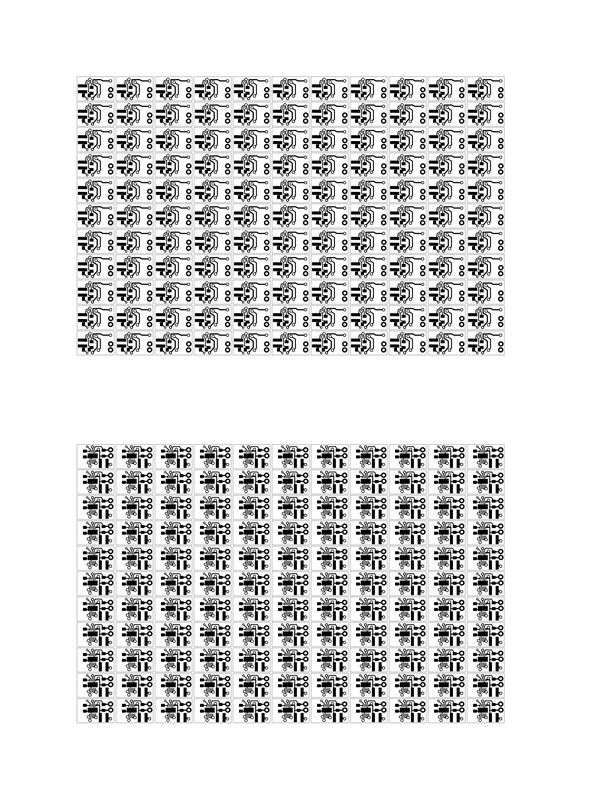
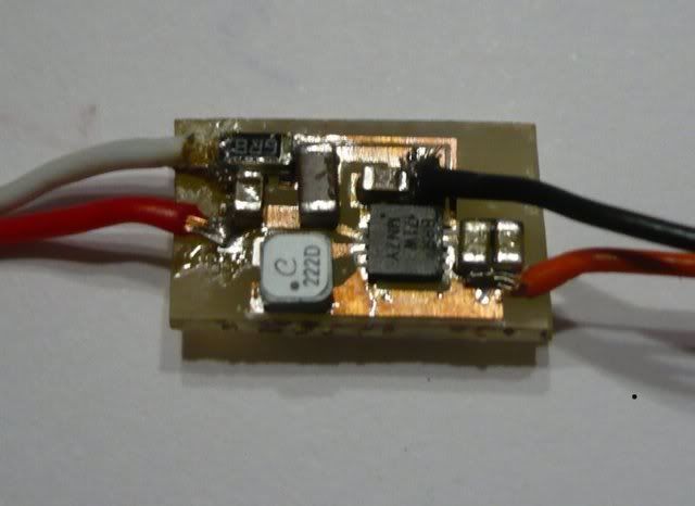
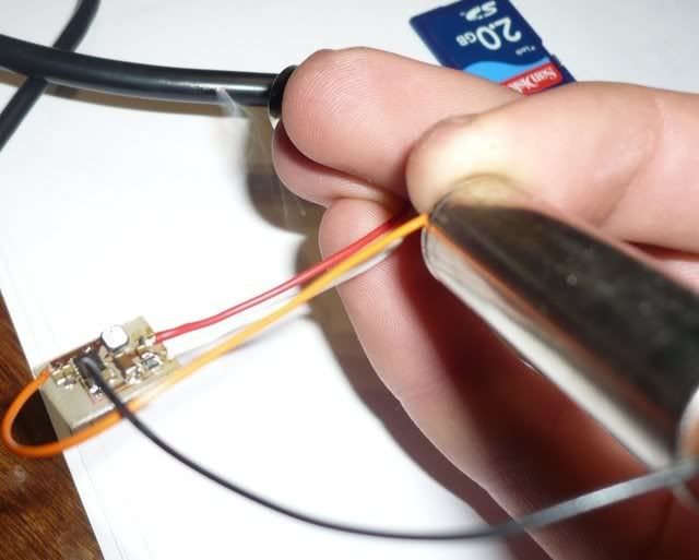
i made up a small board for this chip.
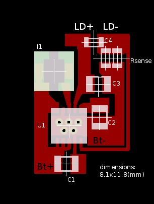
u1= TI TPS61201,
I1= coilcraft LPS3015-222MLB,
C1-3= 10uH ceramic,
C4= low value ceramic,
Rsense= selected using R=0.5/I (where I is the required current).
this driver should not be used without a load.
and LD- must never be connected to Bt-.
power source can be a single AA cell.[/quote]
This is perfect... Almost exactly what I had in mind. Very few external components, etc etc. The only problem is that TI only makes these in qfn packages, making it a little more difficult for the average hobbyist to throw together. Also, what would it take to be able to use the battery ground? And finally, R = .5/I.... this may be an obvious question but I is in amps right? so 200mA would be R=.5/.2 correct?
great work!


