- Joined
- Dec 15, 2014
- Messages
- 6,773
- Points
- 113
Hi,
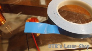
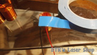
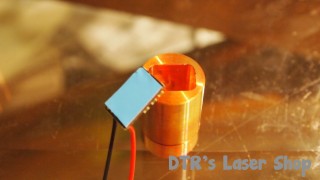
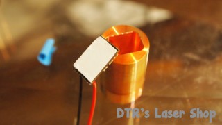
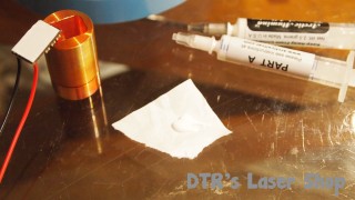
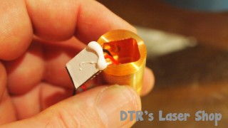
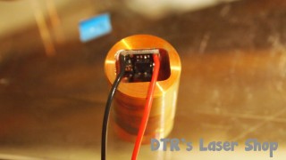
This is how I heat sink the BB drivers, you will see that the CU sink is in-between the diode and voltage pins. And it raises the driver up enough for the driver not to contact the main heat sink. this world perfect on many builds . Hope this helps with Heat sinking these BB drivers, Arctic Alumina is the adhesive compound used here.
Rich")


This is how I heat sink the BB drivers, you will see that the CU sink is in-between the diode and voltage pins. And it raises the driver up enough for the driver not to contact the main heat sink. this world perfect on many builds . Hope this helps with Heat sinking these BB drivers, Arctic Alumina is the adhesive compound used here.
Rich