Welcome to Laser Pointer Forums - discuss green laser pointers, blue laser pointers, and all types of lasers

Buy Site Supporter Role (remove some ads) | LPF Donations

Links below open in new window

FrozenGate by Avery

Blackbuck 8M Driver Heat Sink Advice

Hi,
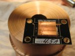
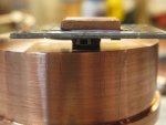
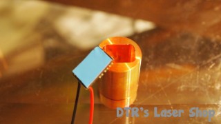
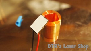
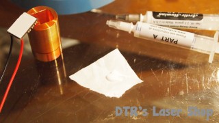
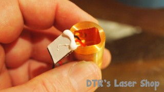
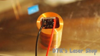
This is how I heat sink the BB drivers, you will see that the CU sink is in-between the diode and voltage pins. And it raises the driver up enough for the driver not to contact the main heat sink. this world perfect on many builds . Hope this helps with Heat sinking these BB drivers, Arctic Alumina is the adhesive compound used here.
Rich:)
IMG_4907.JPGIMG_4908.JPG


@rmarino
Got a message back from X-Wossee. As I suspected and wrote in my reply to you over on ebay the 5V output is only capable of handling a very low current draw and to hold off trying till I heard back as powering a load like that with it might even cause damage. Here is what I got back.
"This output is capable of giving 30-50 mA to the load, I doubt that an abstract "small" fan can be a safe load for this output."
I would find another way to run the fan.🍺

Hi,
This is how I heat sink the BB drivers, you will see that the CU sink is in-between the diode and voltage pins. And it raises the driver up enough for the driver not to contact the main heat sink. this world perfect on many builds . Hope this helps with Heat sinking these BB drivers, Arctic Alumina is the adhesive compound used here.
Rich:)
View attachment 66282View attachment 66283

That will work and will run just fine when you thermally bond it to your main heatsink.

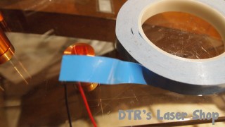
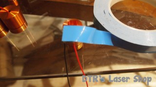
I use thermal tape and arctic alumina two part thermal adhesive around the edges to secure it and electrically isolate the base from the sink. Similar to how it is done with the smaller ACS units mounting to the driver shelf on my 20mm and 25mm copper modules. The IC will be hot but have not seen or had reports of any issues with the thermal tape method although your copper shim might transfer heat a little more efficiently.🍺


Last edited:
Hi,
Yes absolutely these methods will work fine just as long as the older pointe don't touch the the main sink or the heat sink pad.
Done many this way , if your unsure Kempton tape is another option . just make sure your solder points are done to a minimal you dont need a great amount of solder to bond your wire to the driver.
Rich:)
 
Thx, guys. Much info here. I will consider my options and get back to you with the design. However, I will probably add a 30mm fan (powered by the input 12V) as I plan longer runs (engraver setup)
 
The Blackbuck 8M runs very hot even at 4.5 Amps. I can't imagine it could ever run for more than a few seconds at 8 Amps.


This is how I did the heatsinking on my Nubm44 Lab Style build. There are 2 Heat pipes from the 2 IC's to the main sink. The Copper sink was thermally bonded to the diecast case it was all put in. It should run forever at 4.5 Amps.

I did put a Pot on the modulation input so I could adjust the output.
Question:
1) The picture shows 2 chips being heat sinked to the main bottom copper sink.
Do both ICs get hot? I thought the only IC which needed to be heat sinked was the black chip (with the many legs coming out the sides)?

2) In the picture, the smaller chip on the left is the one that gets hot?


Back
Top