Welcome to Laser Pointer Forums - discuss green laser pointers, blue laser pointers, and all types of lasers

LPF Donation via Stripe | LPF Donation - Other Methods

Links below open in new window

ArcticMyst Security by Avery

Black buck 5.5A reverse polarity fuse location

Joined
Jul 9, 2009
Messages
177
Points
28
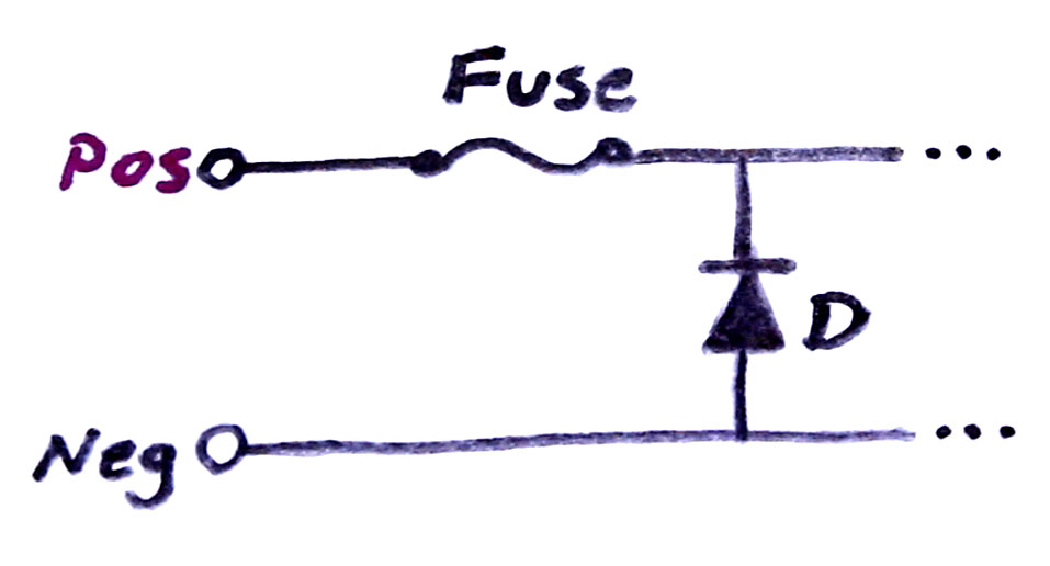
Long-time no see fellas! Getting back in the light amplifier hobby after some time off. I used DTRs excellent service to obtain a num44 V2 and a blackbuck 5.5A driver. I had it working but was testing with two 18650s outside a host and made the rookie mistake of connecting power in reverse polarity(facepalm)! In my defense, I was in the dark oogling at the bright but horribly divergent beam.

I understand there is a ceramic fuse which may save the day. I have SMD rework equipment and good soldering skills, I could check for continuity but I'm multimeterless ATM due to moving. Never let the wife pack tools!!!!!

Anybody give me the location of the fuse. 65557


Joined
Jan 29, 2014
Messages
12,031
Points
113
I had never heard about a fuse on this driver but looking on DTR's web page, I see it does. I would expect it to be the first SMD device inline with one of the two plus or minus input wires, but maybe not. DTR often answers emails the same day.

That white SMD sure looks like a fuse to me, I don't know what else that could be. The convention is to put the fuse on the plus line most of the time, that white SMD is close to the positive or red wire, is it soldered to it, or to a trace which goes directly to it? If so, I'm 99% certain that is the fuse.

 
Last edited:
Joined
Sep 20, 2013
Messages
17,386
Points
113
I was unaware of the fuse as well. You know you can add a silicon rectifier to the input to eliminate reverse polarity problems. I have never had this issue, though.
 
Joined
Jul 9, 2009
Messages
177
Points
28
Thank you! Thats the one I suspected. Guess Ill just jump it until or if I ever get around to finding a replacement. Fish out of water with no meter, guess I could rig something up with a button cell and a led.
 
Last edited:
Joined
Jul 10, 2015
Messages
9,880
Points
113
I was unaware of the fuse as well. You know you can add a silicon rectifier to the input to eliminate reverse polarity problems. I have never had this issue, though.

Why use a fuse in place of a diode to achieve reverse polarity protection ?
The driver would have to take a reverse current until the fuse blew if it was meant to serve as reverse polarity protection, it would use a diode and a fuse, so it likely has a diode as well/already.
 
Joined
Jan 29, 2014
Messages
12,031
Points
113
Only one reason I can think of why use a fuse instead of a diode is to lower the voltage the device can otherwise operate from. That, and a diode will make the regulator less efficient, the voltage drop across the diode X the current through it is lost power. I had a coworker who was a top notch supertech in electronics who had a hole in his knowledge regarding diodes, for some reason he thought there was no power loss when using them that way. They heat up when current goes through them due to the voltage drop, i.e. a silicon diode drops approx. .7 volts. At one amp, that's 700 mw of lost power. I prefer to use Germanium diodes over silicon for such use, as they have about half that amount of voltage drop.
 
Last edited:
Joined
Jul 10, 2015
Messages
9,880
Points
113
Yes .7 -1.0v but if the diode is across the input in reverse then when a backwards current is applied the diode takes the power and blows the fuse, a fuse alone would not be a good idea.
 
Joined
Jan 29, 2014
Messages
12,031
Points
113
Oh, reverse biased insertion across the input instead of in series with it, yep, in that case, no additional loss, it blows a fuse, but then you must have a fuse in addition to that.
 
Joined
Jul 10, 2015
Messages
9,880
Points
113
Yes I was thinking if paul added a diode that it would not be needed and as you said it would raise the Vin as well, I suppose you could add a diode and use a higher Vin to prevent blowing the fuse, I was thinking about how it was made and that a fuse alone would not be a good idea.
 
Joined
Jan 29, 2014
Messages
12,031
Points
113
Well, for myself, I might opt to just design a driver with an inline diode, no fuse to blow, but at a cost to efficiency and raising minimum Vin.
 
Joined
Jul 10, 2015
Messages
9,880
Points
113
Yes a lot of the Chinese drivers do that, the designer was likely going for a lower Vin as you said where I would make it as foolproof as possible for American users.
I wonder what the cost would be for a tiny self resetting breaker ?
 
Joined
Jan 29, 2014
Messages
12,031
Points
113
I wonder, if you can develop it, you might be creating something which would be a money maker as I've never seen something small enough to integrate onto a circuit board small enough to fit inside an Axis module. I suppose if we can imagine it, someone makes it, or can?
 
Joined
Jul 10, 2015
Messages
9,880
Points
113
I'm sure there is much made that I have not yet seen, probably such a thing is obsolete already. :)
Just a thought, rather than a silicon why not a schottky diode if used in series ?
 
Last edited:
Joined
Sep 20, 2013
Messages
17,386
Points
113
I immediately thought, after my post, that a Schottky diode might be a better option. Much lower Vf and higher current.
 
Joined
Sep 12, 2007
Messages
9,399
Points
113
Simple rectifiers are stupid for high power applications, as that's a waste of 4W of power, and now you need to heat sink something else. This is "when all you have is a hammer, everything looks like a nail" thinking. Expand your electronics knowledge before suggesting such 1970s solutions, please. At least google reverse polarity protection - there are vastly superior methods these days. Even something this simple is way better:

Fuse-Reverse-Protection.jpg
 
Joined
Sep 20, 2013
Messages
17,386
Points
113
Selecting the right Schottky diode will reduce your loss by about a third. Another way to do the is to use a P channel MOSFET. Connect the drain to the positive terminal and the source to the positive input of your driver. If the SG breakdown voltage is high enough, you can just connect the gate to the negative terminal of the battery or driver input. Very easy and your losses will be very small in comparison to any diode. If you choose a MOSFET with too low a SG breakdown voltage, you can still get by with the addition of a Zener diode and a gate resistor.


Top