- Joined
- Jun 21, 2012
- Messages
- 85
- Points
- 8
I have the 405nm diode extracted. It´s supposed to reach 500mw.
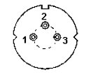
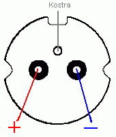
I have been deep searching for the pintout of this diode and the only suggestion found is that should be like other high power 405 LD. The info is supplied by Danguin:
The assumption is what afraids me. More in this case, as the diode has only 2 pins (no 3rd cutted pin, that diodes are designed with only 2). The diode is 3.8mm
So Im thinking in running a small current, let´s say 1.5v, 100ma throught the led and the amperimeter to test polarity... do you think it could damage it? Any safer suggestions?.
Once I, hopefully have determined the pinout, I would like to listen your sugerences about a max safe current. The LD is going to be housed in a 12x30mm aluminium aixiz, with a little fan near in an aluminium bigger box.
Do you think 400mA would be dangerous?. As long as I dont have LPM... maybe I should start at 250ma and slowly going up tracking with my fingers until the module get warm but not hot?.
Hopefully I could report the definitive pinout and some orientative acceptable currents for the building. As long as I have research, this is the cheaper high power 405 diode available and this info could be useful for future amateur builders and hobbist. :angel:
More info about this sled (maybe the only info in the web):
http://laserpointerforums.com/f38/bdxl-pioneer-bdr-206m-63328.html
The sled was purchased at lazerer
I have been deep searching for the pintout of this diode and the only suggestion found is that should be like other high power 405 LD. The info is supplied by Danguin:
(Thank you Daguin!)I have NOT tested it under power yet. I am still waiting for someone to fabricate a module for me. My assumption (and the one I will work with first) is that the pinout for this diode is the same as for the 8X/10X/12X.

The assumption is what afraids me. More in this case, as the diode has only 2 pins (no 3rd cutted pin, that diodes are designed with only 2). The diode is 3.8mm
So Im thinking in running a small current, let´s say 1.5v, 100ma throught the led and the amperimeter to test polarity... do you think it could damage it? Any safer suggestions?.
Once I, hopefully have determined the pinout, I would like to listen your sugerences about a max safe current. The LD is going to be housed in a 12x30mm aluminium aixiz, with a little fan near in an aluminium bigger box.
Do you think 400mA would be dangerous?. As long as I dont have LPM... maybe I should start at 250ma and slowly going up tracking with my fingers until the module get warm but not hot?.
Hopefully I could report the definitive pinout and some orientative acceptable currents for the building. As long as I have research, this is the cheaper high power 405 diode available and this info could be useful for future amateur builders and hobbist. :angel:
More info about this sled (maybe the only info in the web):
http://laserpointerforums.com/f38/bdxl-pioneer-bdr-206m-63328.html
The sled was purchased at lazerer
Last edited:


