very interesting .... thanks .... may it be moved to a Raman Spectrometer threat ?

Welcome to Laser Pointer Forums - discuss green laser pointers, blue laser pointers, and all types of lasers
How to Register on LPF | LPF Donations
Navigation
Install the app
How to install the app on iOS
Follow along with the video below to see how to install our site as a web app on your home screen.
Note: This feature may not be available in some browsers.
More options

You are using an out of date browser. It may not display this or other websites correctly.
You should upgrade or use an alternative browser.
You should upgrade or use an alternative browser.
B&W-tech Spectrometer & 473 module: Setup+Mods+Info
- Thread starter jnrpop
- Start date


jnrpop
0
- Joined
- Dec 7, 2008
- Messages
- 728
- Points
- 63
Hi jnrpop, could you please post the startsequence of the device by using a serial-command tool , i would be interested in the selftest passing code at the end.
I have sent you such a tool, it is on the stick ....
Hi chloderic,
I tried using the Te....ite software you placed on the usb, but I can’t seem to read the start sequence or anything when the spectrometer is connected. Is there a command line I need to enter into the Te....ite software to register the spectrometer and the correct port?
O, I also got the Spectrometer to register again on Moscs software and the original B&W software, but still get the same message when using Speactral Studios.
It could be possible the Spectral Studios software we have has a license time frame or error with registration?
J :beer:
- Joined
- Sep 20, 2013
- Messages
- 20,284
- Points
- 113
I haven't had one of these out in a long time now. I guess I ought to see if the software I have for them still works. Last time I got one calibrated and running on the Science Surplus software and it was okay for the most part. That was where I left it. Might pull it out this weekend and see if it is still working.
Hi chloderic,
I tried using the Te....ite software you placed on the usb, but I can’t seem to read the start sequence or anything when the spectrometer is connected. Is there a command line I need to enter into the Te....ite software to register the spectrometer and the correct port?
O, I also got the Spectrometer to register again on Moscs software and the original B&W software, but still get the same message when using Speactral Studios.
It could be possible the Spectral Studios software we have has a license time frame or error with registration?
J :beer:
Hello, yesterday I had to work and therefore could only look up today ...
Spectrum Studio works fine.
Here is the procedure with the terminal prgm:
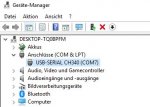
If you do not know yet, which COM port is used and you have several, you can look in the device manager of windows, see 1. picture in the system,
In my case, it is only com7, you can also use the ingenious software of Mosc007, top left should be the com-port used.
If you have no other com port except usb / ser, you do NOT need to look here, then in the terminal program only this one is displayed.
- first connect the ser / usb stick to the pc and spectrometer and the power supply to the spectrometer and start the terminal software.
In the terminal program you now have to set under settings the following parameters (see second pic.) :
COM7 (with you probably just another port)
baudrate 9600
databits 8
stop bits 1
parity none
- in the upper menu bar you should see either Disconnected - click to connect, then "click", or the entered data can be seen there.
The self-test of the spectrometer runs in post, which means so in the first 3 seconds after the power on and ends with color change of the led to red.
This POST you can see only in these 3 seconds, which means again, you must now disconnect the power supply from the spectrometer, but leave the serial cable connected.
Now plug the power back on and you'll see this post in the first 3 seconds with a pass code at the bottom.
Attachments
jnrpop
0
- Joined
- Dec 7, 2008
- Messages
- 728
- Points
- 63
Success, i got the terminal program to identify my Spectrometer, heres the last section of code:

J :beer:
Ok , thanks , to your question obove ... the device /bios seems to be ok. Now i would try to reinstall /update net-framework .
jnrpop
0
- Joined
- Dec 7, 2008
- Messages
- 728
- Points
- 63
re-installed the spectrum studio software and........................no more error 
Must of been a corrupt file in the software folder, or a file location error but my Spectrometer is back up and running, and ive discovered the Calibration info must be stored on the Device/Spectrometer itself, not stored in the software.
Which is great in my opinion because after a fresh re-installing of Spectral Studios, my Spectrometers calibration data was still installed ++++1 :beer:
Thank you for the help chloderic :beer:
Must of been a corrupt file in the software folder, or a file location error but my Spectrometer is back up and running, and ive discovered the Calibration info must be stored on the Device/Spectrometer itself, not stored in the software.
Which is great in my opinion because after a fresh re-installing of Spectral Studios, my Spectrometers calibration data was still installed ++++1
Thank you for the help chloderic :beer:
Last edited:
I am working a little bit with my last mod and would like to discuss in this way about some solutions of other members.
Fist question please to kecked:
You was able to get acess to 2000nm with this grating by only rotating it ?
I have seen it in your profile "BW TEK-2000nm/800nm/400nm moved gratings"
Could you please post some pics and a description how you did this, what type of grating is installed in your device to cover these?
What is please the resolution you got ?
I now , it is a lot af work to document something like this, but i am holding in this project, because i am not able to find such a solution.
Thanks a lot ...
- Joined
- Jun 18, 2012
- Messages
- 1,046
- Points
- 83
I really can't say anymore. It's all in a box somewhere. Once I got the Ocean Optics unit I just never went back. I used the stock grating for 1100-400 and a 600L one for the 2000nm. It was not great resolution. maybe guessing 1-2nm but more like 2-3nm. All I had in that range was some IR leds in the 1.69 and 1.89 range. I saw them but the source is wide. I also could barely use my fiber.
I just glued the grating in place a cut off the excess with side cutters. Not real scientific.
I just glued the grating in place a cut off the excess with side cutters. Not real scientific.
Thanks, the printer is a clone of an ultimaker 2+ extended. I had an original UM2 a few years ago and fell in love with them. These days it is hard for me to justify the cost of the true UM2sI think the layer height was .15 for this print (cura default).
The alignment of the fiber optic connector did not cause me any issues. The power connector on my spectrometer lined up with the left side of the hole, however the connector housing on the cable was bigger than the hole. Even if it had lined up in the center, this cable wasn't going to fit so I had to enlarge the hole post-print. I've seen barrel plugs with much thinner bodies so for me, this wasn't a design issue
Hope that helps
Dear Agastar,
Can you please, send me the Autofusion file, so i can addapt it and make some changes (that i will post here of course).
espcially for the holes, i would like to pin point their exacte position.
Please, it is quite urgent .. many thanks for sharing
C
Bit of a long shot, but hoping someone here may be able to help.
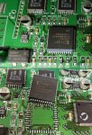
Anyone have any scrap B&W spectrometer PCBs from one of these units, perhaps with mechanical damage or missing / damaged optical assembly? Specifically I’m looking to recover one or two pieces of U401 IC, Xilinx XC9536. This is a B&W programmed part so can't just get one from Farnell.
A bit of background - I’ve been passed a friends spectrometer to repair. It had been connected to 12V rather than 5V.
When I powered it from a bench PSU set to 5V, 1A limit, the PSU went to current limit at just under 1V.
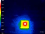
Thermal photography showed only one IC getting hot, that being the Xilinx XC9536. Removal of this IC returned current consumption to near normal, and allowed communication via RS232, indicating a fair chance of returning to normal operation if U401 is replaced.
Thanks in advance...
Robin
Attachments
- Joined
- Jun 18, 2012
- Messages
- 1,046
- Points
- 83
I had the same thing happen but the device never saw over 5V and used their own power. Smelled horrible. I may have a couple spares. I gave up and went to Ocean Optics. Message me info to send if you are in the USA. If you are not in the USA it will cost more to ship then buy new off ebay.
- Joined
- Jun 18, 2012
- Messages
- 1,046
- Points
- 83
Appears your right. I guess I better hold on to what have. I took for granted that they would be around for a long time. Wonder if they just took vacation and didn’t list.
- Joined
- Sep 20, 2013
- Messages
- 20,284
- Points
- 113
I made this same mistake when I was looking for the voltage to run one of these and found an eBay source that showed a +12 volt wall wart as the power supply. The optical bench is fine, but the PCB is toast and without a schematic, it wasn't worth my time to chase down the dead short on that line now. I may change my mind at some point and start disconnecting devices on that line to find the short. But, these have turned out to be less than optimum spectrometers.


