Welcome to Laser Pointer Forums - discuss green laser pointers, blue laser pointers, and all types of lasers

LPF Donation via Stripe | LPF Donation - Other Methods

Links below open in new window

ArcticMyst Security by Avery

B&W-tech Spectrometer & 473 module: Setup+Mods+Info

Joined
Sep 20, 2013
Messages
17,438
Points
113
No problems here. Not a disagreement either. I have spent a fair amount of time trying to get these to be more accurate. Trying to get to 0.1nm of accuracy may be beyond the ability of these to accomplish. But, the work goes on. :yh:


Joined
Jan 21, 2018
Messages
324
Points
43
Gentleman/ladies...not sure really, I posted that because I was subtly asking for help aligning the bw Tek system. I think they should be able to match the ocean optics units. I think they just need a lot of alignment help. While I did go hr2000, I still want to make these the best possible. Sorry, I will be more direct in the future. Didn’t means to start a disagreement as one doesn’t exist.

Hello, no, we certainly did not argue here in the negative sense.
A little bit of discussion is helpful as always to encourage progress.
All is well ......

Now to the next topic ...:
I have tried to analyze the structures of the grating, which is quite difficult due to the fine structures.
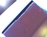
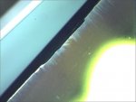
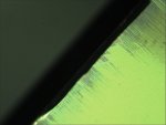
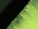
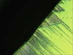
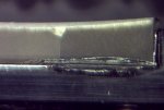
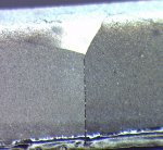
Here are various pictures of the edge of the installed 1800 grating.
You can see the fracture edge, the frayed coating structures in the edge area because apparently this grid is additionally coated on the surface.
Please do not be scared, such large magnifications always look pretty brutal in detail.
Please also keep in mind that here you can see details in the order of about 1/2000 mm!

:beer:
 

Attachments

  • 06.jpg
    06.jpg
    295.2 KB · Views: 28
  • 1.jpg
    1.jpg
    300.9 KB · Views: 28
  • 2.jpg
    2.jpg
    346 KB · Views: 27
  • 4.jpg
    4.jpg
    357.8 KB · Views: 29
  • 7.jpg
    7.jpg
    400.1 KB · Views: 31

kecked

0
Joined
Jun 18, 2012
Messages
952
Points
63
I wonder if that is just oxidation. I’d be willing to try various cleaners in an ultrasonic bath to see what happens. I have a feeling the grating has degraded. Maybe try to replace it with a new one off eBay. Can you get a Raman signal off the grating to see what that coat is made of? Really need xrf to see that. I th8nk you found why they differ and if it’s just a grating change out so be it.

Do you have a way to measure flatness? Not sure how on a ruled surface as the roiche lines will not be visible. I don’t have a running ellipsometer to evaluate the thin film.

Feeling experimental
https://www.researchgate.net/publication/38044395_Grating_interferometer_for_flatness_testing

Do you think the grating is silvered? Could require a ne2 coat but I think it woul$ be to thick and require sputtered alum.

A quick dip in tarnex and then soak in baking soda might do it. Try ultrasonic with soapy water first.

A trick to put the grating back at about the same position removed is make two or more scratches on the base of the grating and the base of the unit. If you line them back up by eye you should be very close.

Clean d a grating with rodi water and then in ultrasonic with a little windex. Looks very nice. Few scratches but tok the fog off. Seems pretty much the same as before no difference.

I have two units now that stopped working one smoked and the other just won’t light up. The smoked one I dropped before the smoke. So I have parts if needed and can afford a few cleaning experiments. The other optics are perfect.
 
Last edited:
Joined
Sep 20, 2013
Messages
17,438
Points
113
I would not try to clean anything in the optical bench. You will likely cause more damage than any improvements. You can try to replace the grating, but I would not touch it at all.
 

kecked

0
Joined
Jun 18, 2012
Messages
952
Points
63
I was able to clean the grating with windex and rodi water. Looks much better. Works exactly the same.

I now have two dead specs. Th electronics just stopped working. The power supply is fine. One smoked and one just stopped working. Wonder what happened. Had not heard of this before. Well got spare parts now. Using these in a class is starting to look like a poor idea. Way to much trouble.
 
Joined
Jun 28, 2018
Messages
8
Points
3
Hello! I have been playing with this model and re-designing compensation optics for taking the filter out. I got a bunch them under fabrication. Kindly advise if anyone is interested in using my design.

Sincerely,
Dan
 
Joined
Sep 20, 2013
Messages
17,438
Points
113
You'll have to be more specific about what you are doing to remove which filter. The bandpass filter in the slit is already easy to remove as are the baffles that decrease the CCD's bandwidth. If this is a Raman design, this is the wrong thread. Otherwise, I have no idea what you are talking about.
 
Joined
Jun 28, 2018
Messages
8
Points
3
When you remove LPF, there will be focus shift and make the aligning process tedious. So why not design a compensation optics?
 
Joined
Sep 20, 2013
Messages
17,438
Points
113
I'm willing to listen to your theories on this and see what you have done to compensate for it. I haven't personally found a focus problem after removing the filter. I can resolve every active pixel in the CCD after its removal.
 
Joined
Jun 28, 2018
Messages
8
Points
3
Did you realign the focusing mirrors (both the input and the one after grating)? I suspect there should be significant degradation in resolution without properly align/compensate the focus. I am getting my spectral calibration lamp setup in a few days. It would be interesting to see the filter's effect on resolution.
 
Joined
Sep 20, 2013
Messages
17,438
Points
113
No, it hasn't been necessary to realign any part of the optical bench after removing the filter. This is not my first experience with spectrometers. I have an Ocean Optics USB2000+ that I have been using for nearly four years. The alignment on two of these B&W TEK spectrometers is fine. The rest I haven't done anything with yet. Another member here has purchased an Ocean Optics HR2000 and you can ask him if he has had alignment problems with these spectrometers. Some of these have come with parts in the optical bench that were loose and clanking around inside the bench, so there have been problems with some of these units, but it wasn't because of the filter removal.
 

kecked

0
Joined
Jun 18, 2012
Messages
952
Points
63
Filter removal by taking the slit out is nothing. Realigns fine. Removing the baffles same just be careful. Moving he grating usually ok with no issues. I do not recommend messing with the mirrors unless you can see the spectrum is off on the detector. Go very slow if you move anything.

I used a very bright halogen flashlight and shined it down a fiber. I looked at the resulting rainbow on the detector to see if it was off or tilted. I have three units and all where fine BUT. I did have a loose mirror on one that I had to glue back in place with superglue. make sure to let the glue dry with the top off or you will fog your optics. even that one really didn't need a tweak but I gave it one. Worked fine.

Go slow and resist the tempation to play unless you really need to.

I didn't do this but you might. Pop a 473nm laser on it and a 632 laser on it at the same time. Look at the peak and tweak for max power on both lines. SHOULD in theory make sure the spectrum hits the detector with max energy and the spectrum is level with the detector. I made this up so your mileage may very A LOT.
Goes with out saying but do this in a dark room. The sensor is unbelievably sensitive.
 
Last edited:
Joined
Sep 20, 2013
Messages
17,438
Points
113
I shouldn't have to say this as most should know it already, but you can't have your peaks getting clipped by allowing too much light into your fiber optic cable. If you have a flat top on any peak, don't measure it as a calibration point. It will be off.
 
Last edited:
Joined
Jan 21, 2018
Messages
324
Points
43
I want to quote to an other treat "Spectrometer Calibration"

The third polynomial regression has worked fine for calibrating spectrometers for a long time now. If you are having problems with fitting the curve, it might be an astigmatism of the light hitting the CCD. As long as your alignment is spot on, this should work for your purposes.

Yes sir, I'm afraid of that, i have to try an other of this devices.

I have now found out why I was so distressed with one of the spectrometers during calibration.
With this device too, the focus mirror has a hairline tear that is invisible to the naked eye.
Of course, this crack deformed the image in the image plane.

Well, then I have now also here more parts to exploit.

This bears my already described impression that I had received with these 6 devices unfortunately tested committee ware.
maybe science-surplus did not want this .....?
 

Attachments

  • 1.jpg
    1.jpg
    366.8 KB · Views: 24
  • 4.jpg
    4.jpg
    420.6 KB · Views: 25
Joined
Sep 20, 2013
Messages
17,438
Points
113
Several of these sold on eBay have turned out to have defective optical parts in the bench. If it is possible, a microscopic examination of each one should be done when having any problems with calibration. I have two, so far, that seem to be okay and a couple more to try to calibrated eventually. I had one sent to me where the focus mirror had detached and was just knocking around inside the bench.

Since the curve of the focusing mirror is adjustable, it is not surprising to see this small crack in one of them. It has likely been adjusted too far at one time.
 
Last edited:

kecked

0
Joined
Jun 18, 2012
Messages
952
Points
63
There is a reason I went and bought the hr2000. I had enough screwing around. Was fun initially but then I just wanted to get my work done.


Top