Hi Guys
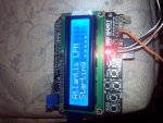
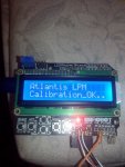
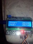
I am building a laser power meter based around an arduino uno and a 16x2 shield and with an external adc commonly found ads1115. i am using a 10mm tec with a pre amp composed of FET's to reduce noise.
At the moment it is very basic but i shall add more features to it. the best thing is that i shall donate it to this forum as as anyone can build it easily.
pic's to follow !


")