Pman
0
- Joined
- Nov 28, 2012
- Messages
- 4,441
- Points
- 113
Received my data logger from ARG a couple days ago. I will also be getting an ARGMeter for Ophir sometime after he gets back from vacation.
As always with me, this is me messing around and I may change anything at anytime.
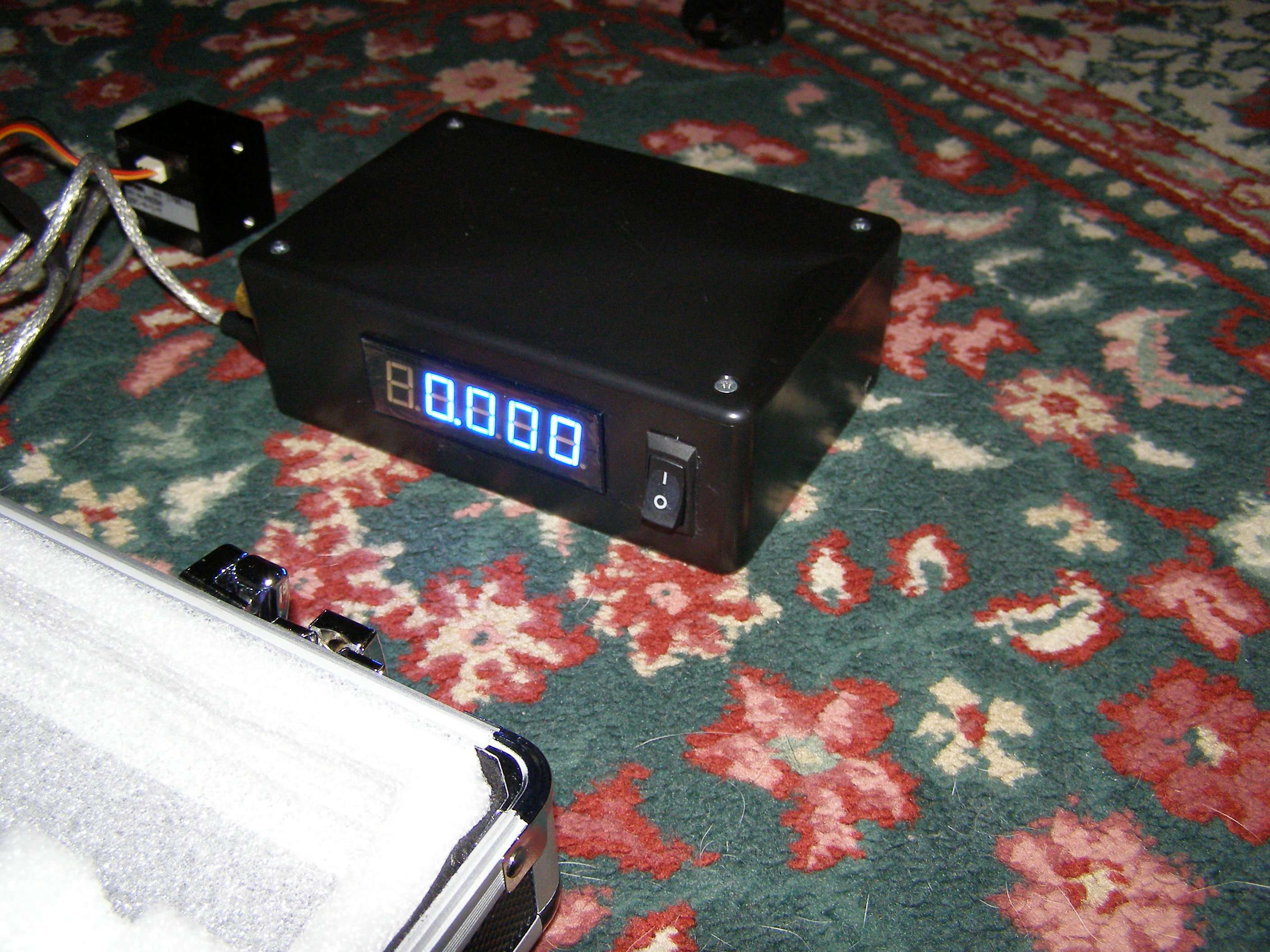
I was trying to decide what to do with the data logger to make it somewhat protected and easily hooked up to either of my LPMs. Had originally made both the TEC based and Ophir based LPMs so they could easily be hooked up with alot of options (I'm heavy on options). So these are a few pictures of the units so you can see why I did what I did for the data logger.
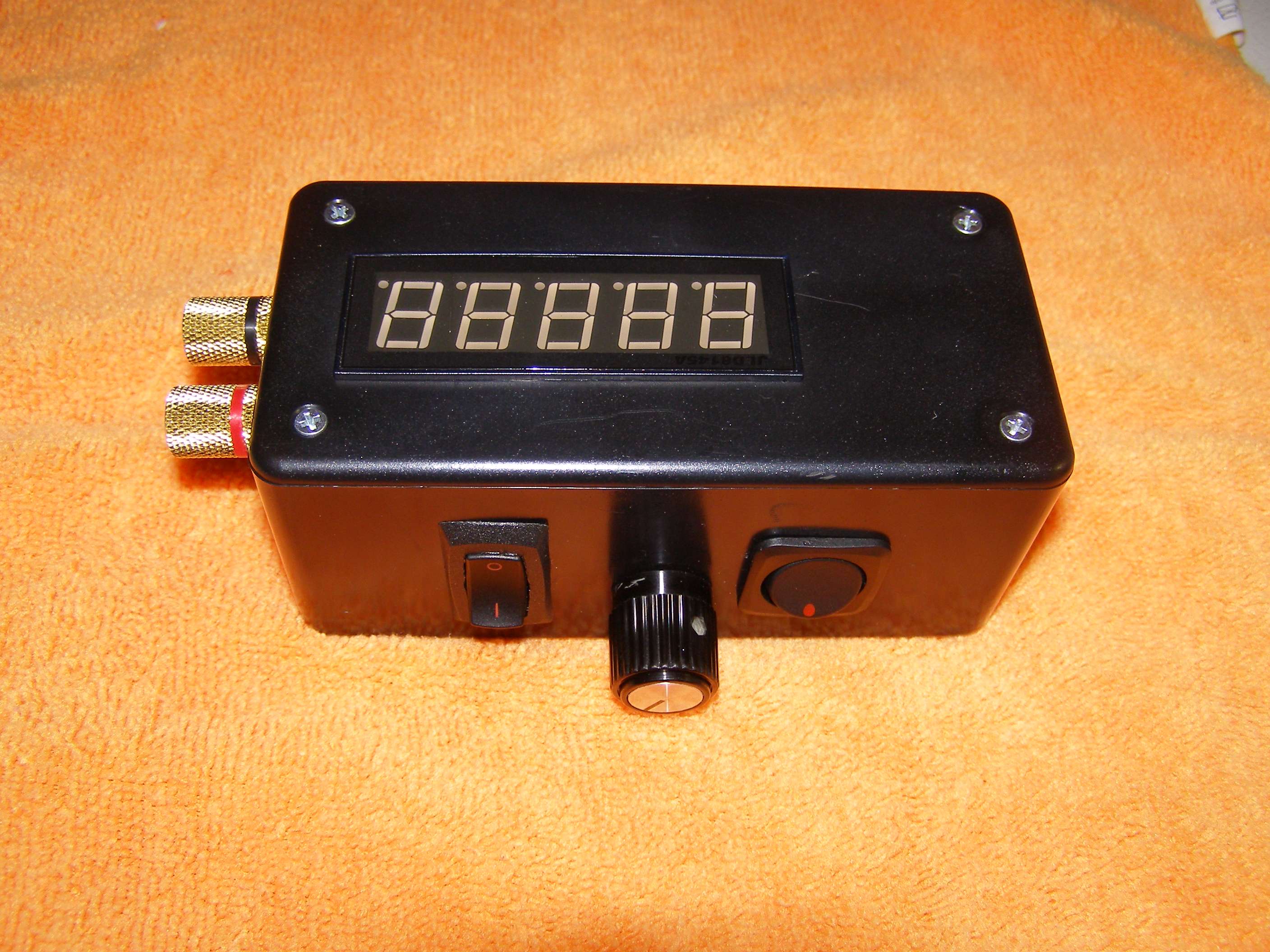
Both units have switchable displays and banana plug compatible outputs.
TEC based unit:
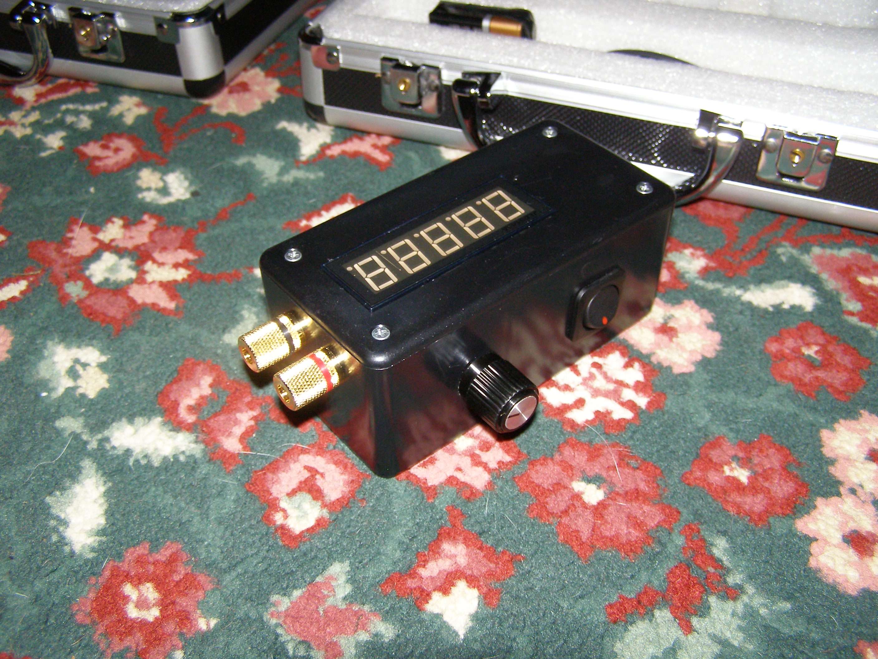
Ophir based unit:

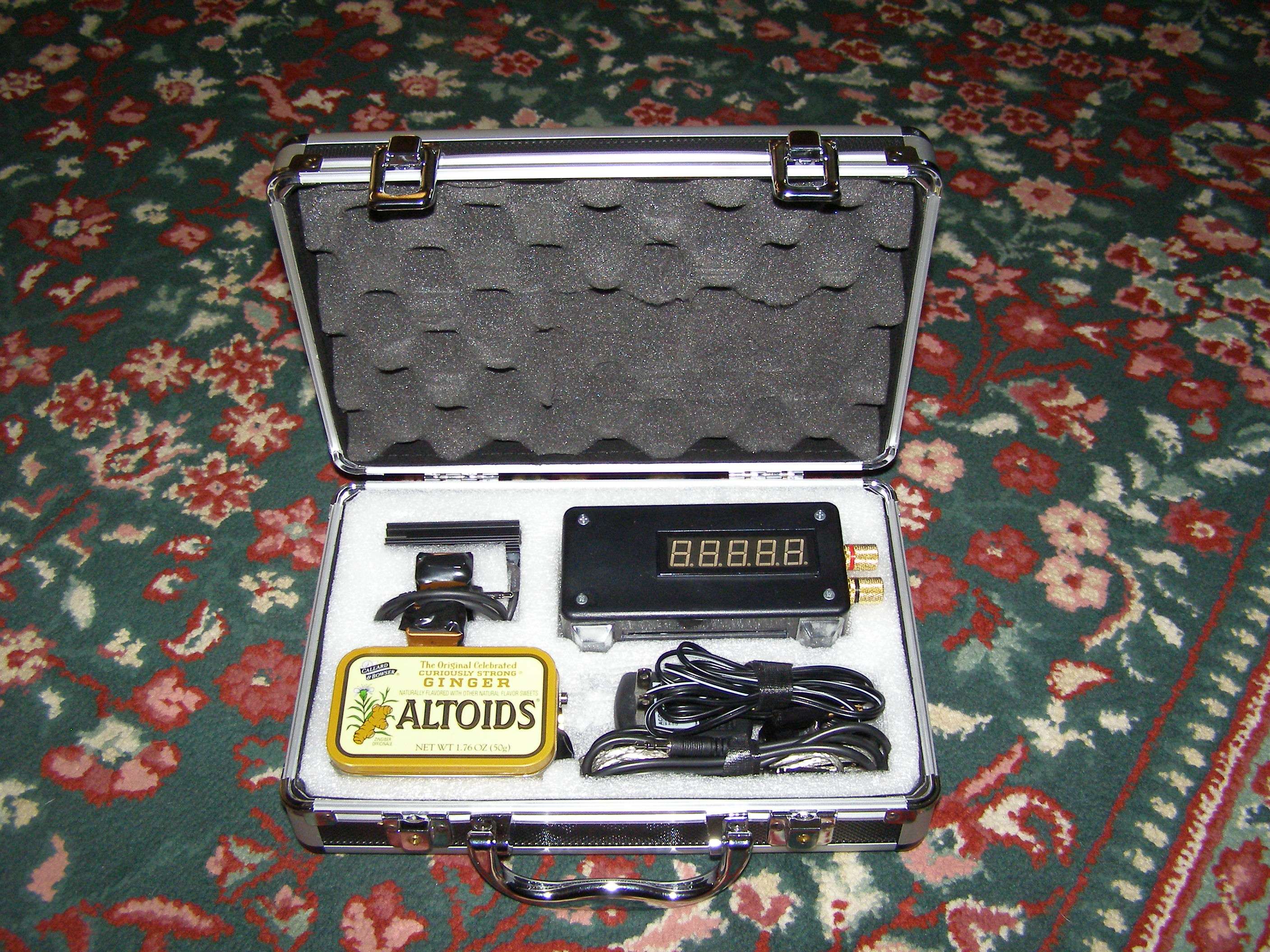
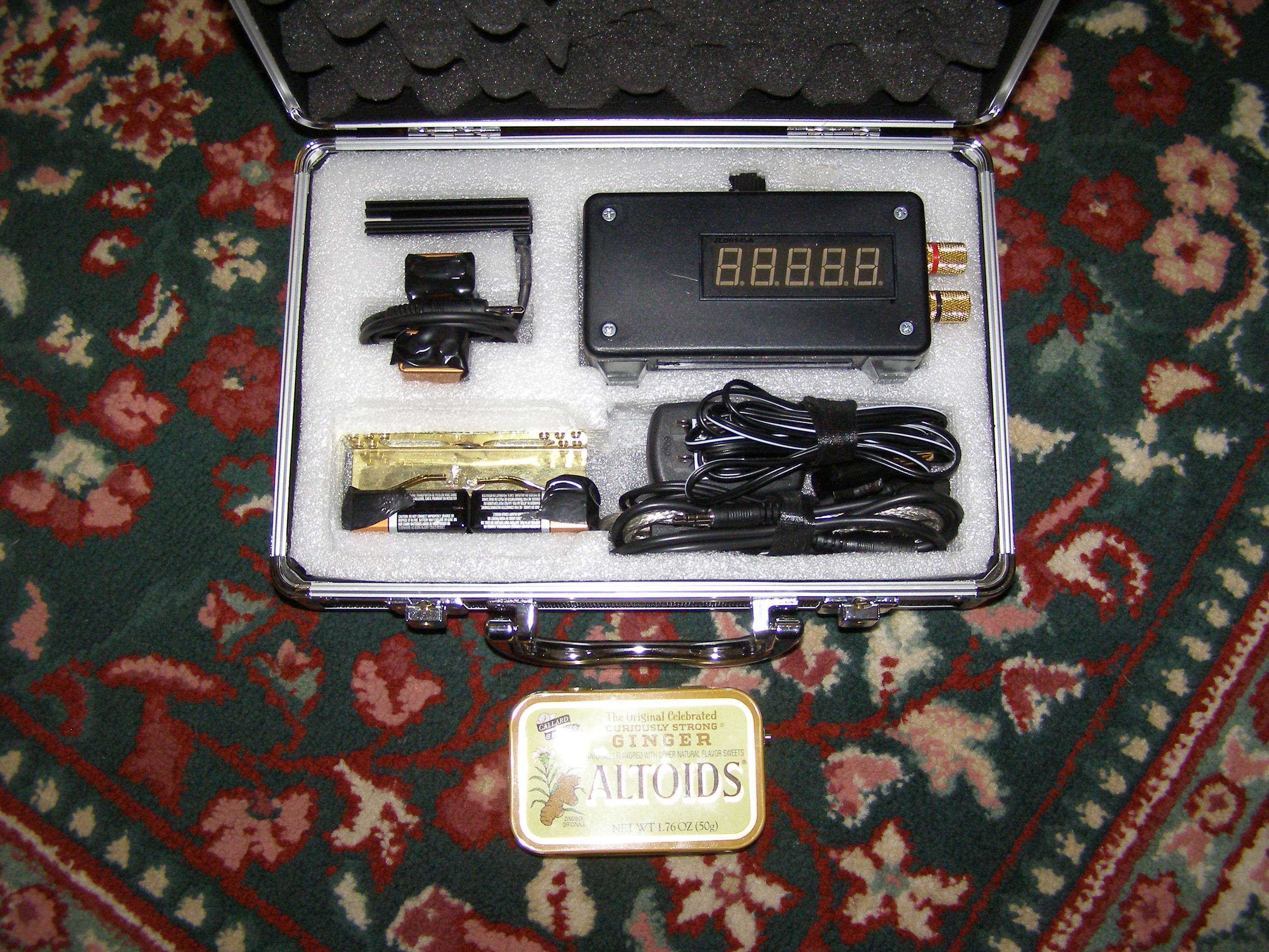
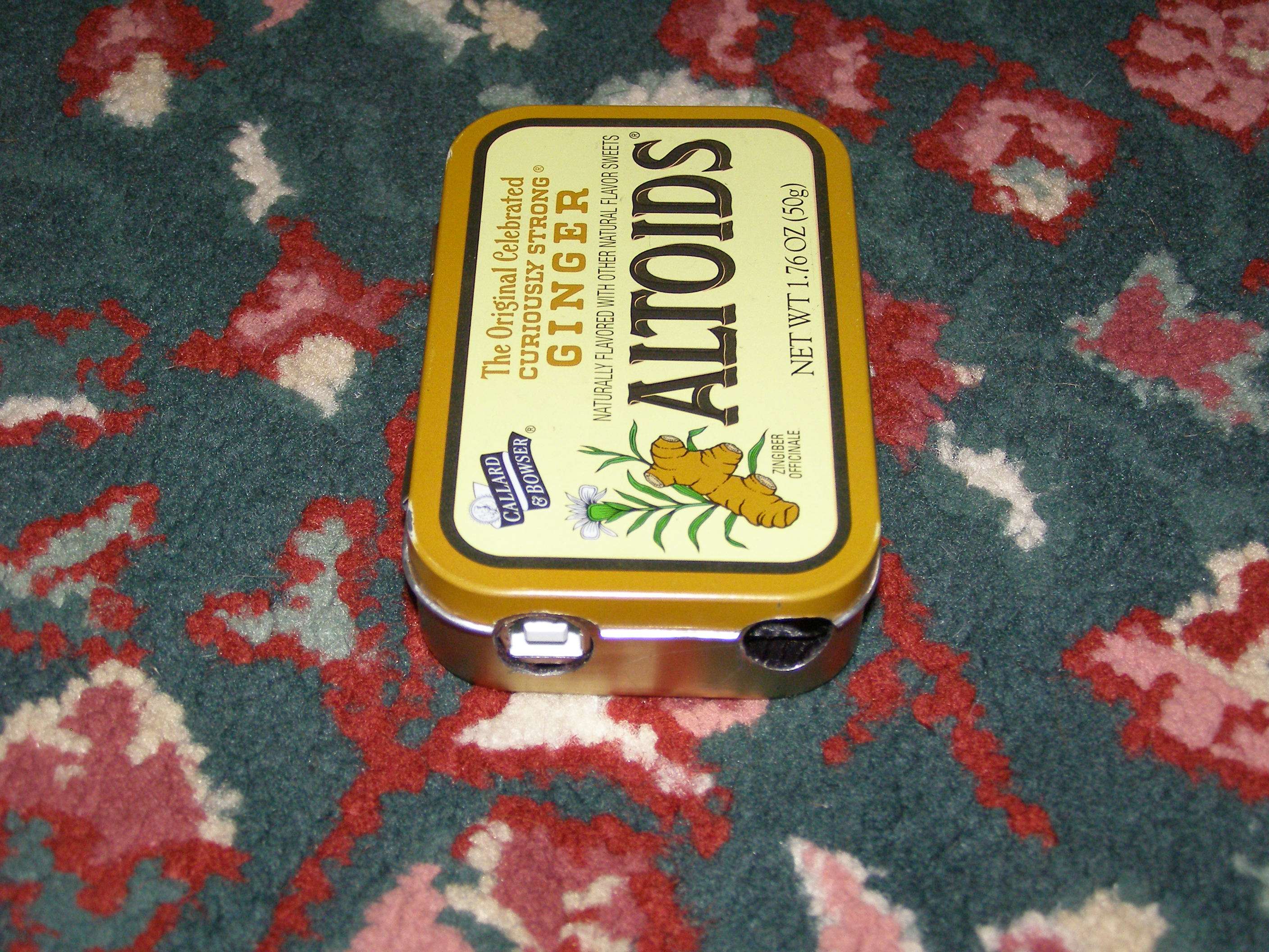
This is what I did with the data logger:
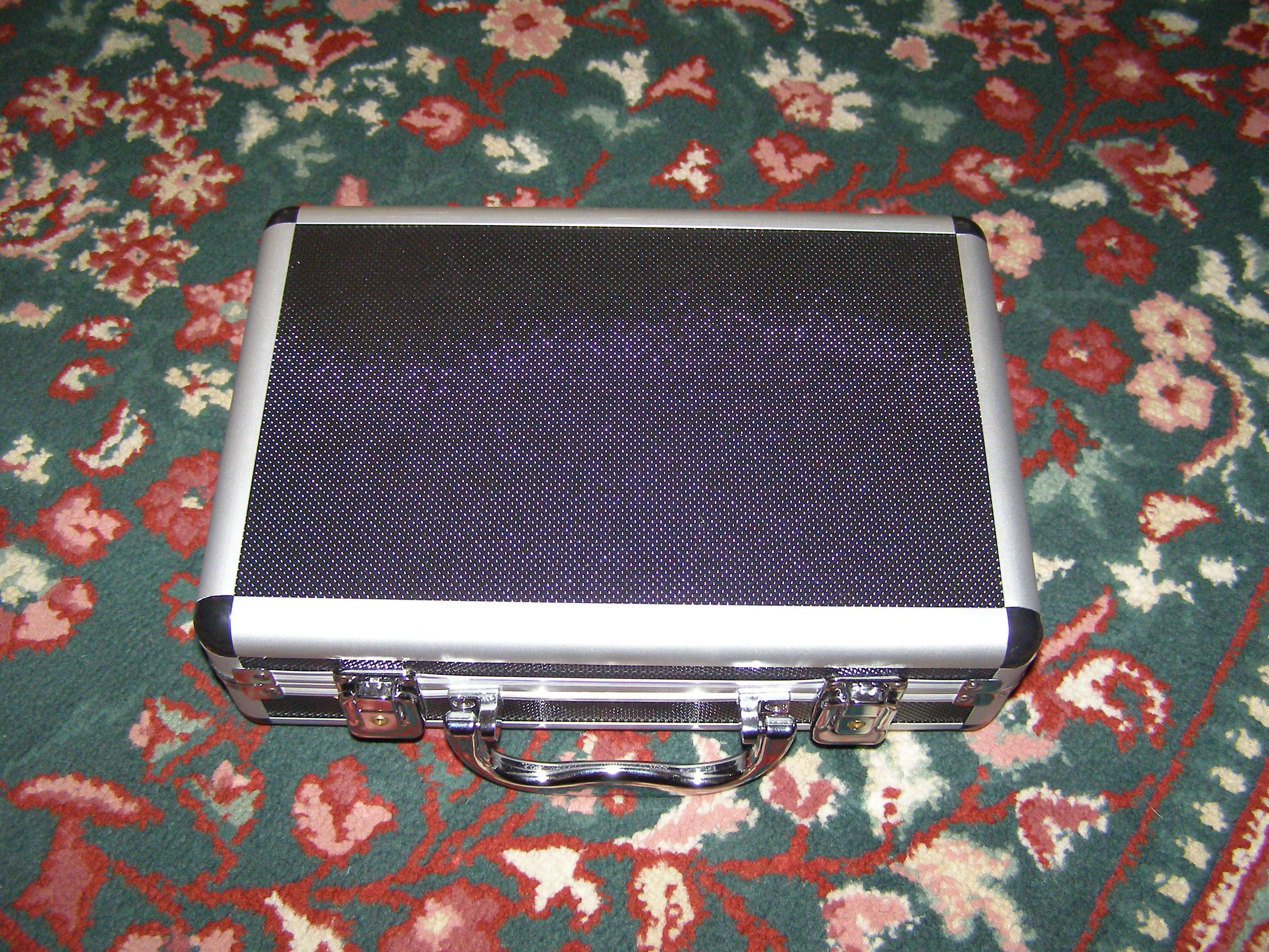
Altoids can (don't necessarily have to use this flavor)

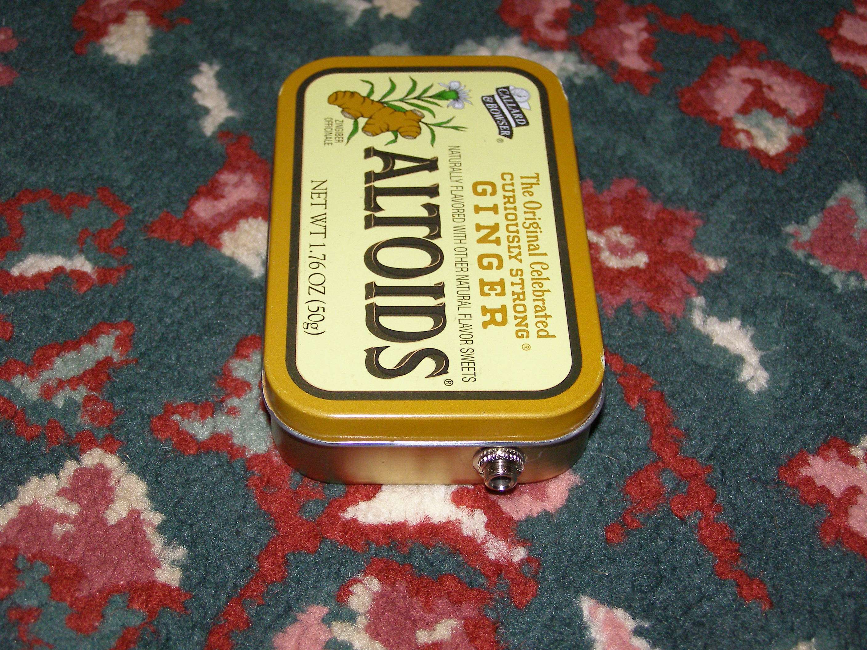
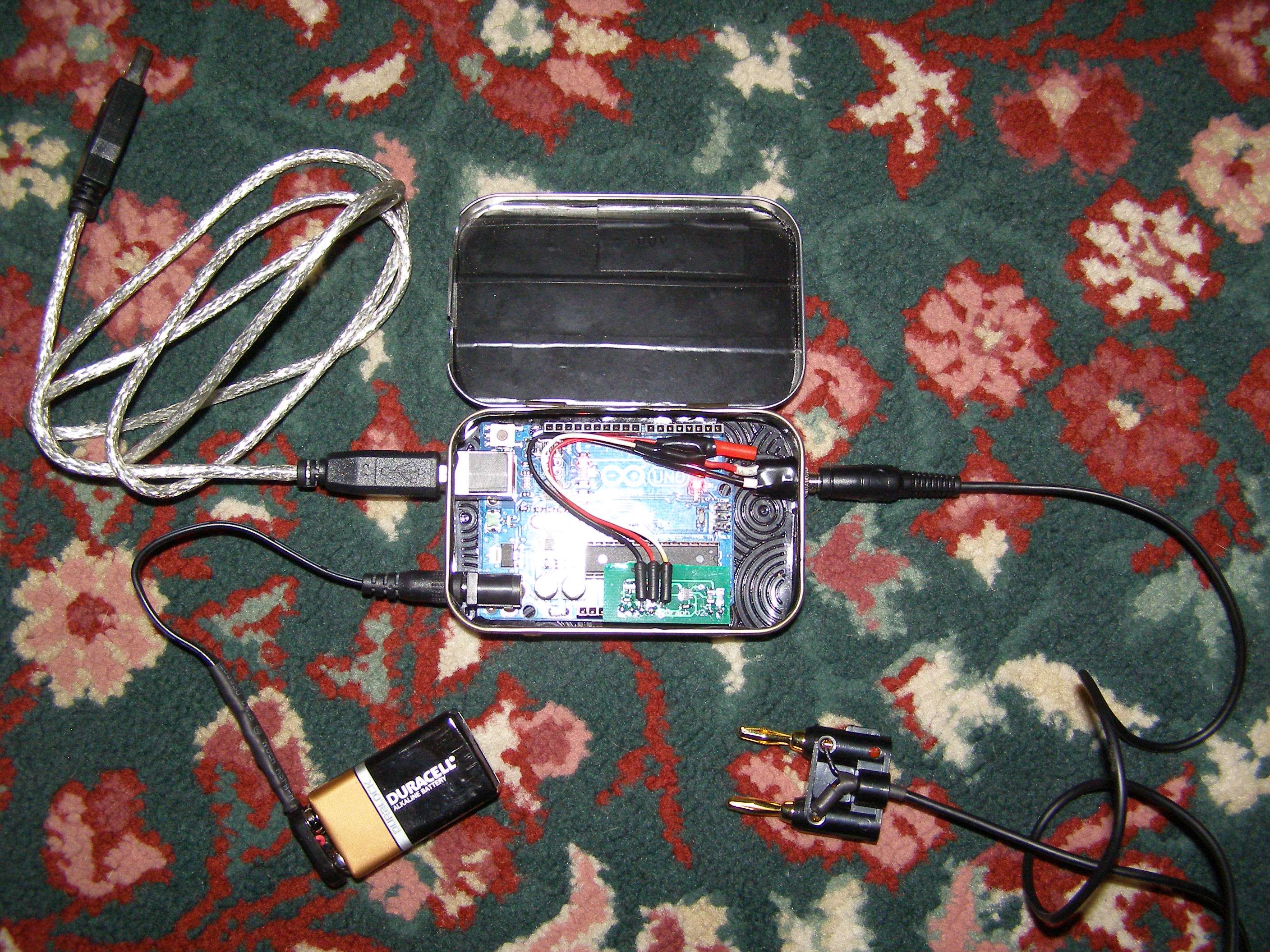
Side view showing holes for USB and Power connector
Standard 1/8" mono headphone jack
Insulated and very well fitting box. Very secure
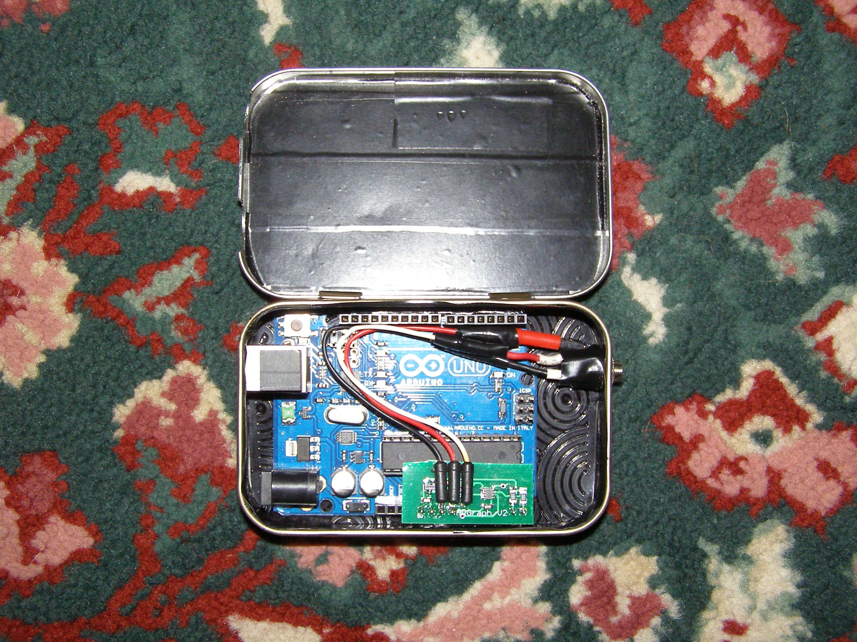
Wires routed out of way of indicator lights (red Vin wire not used)
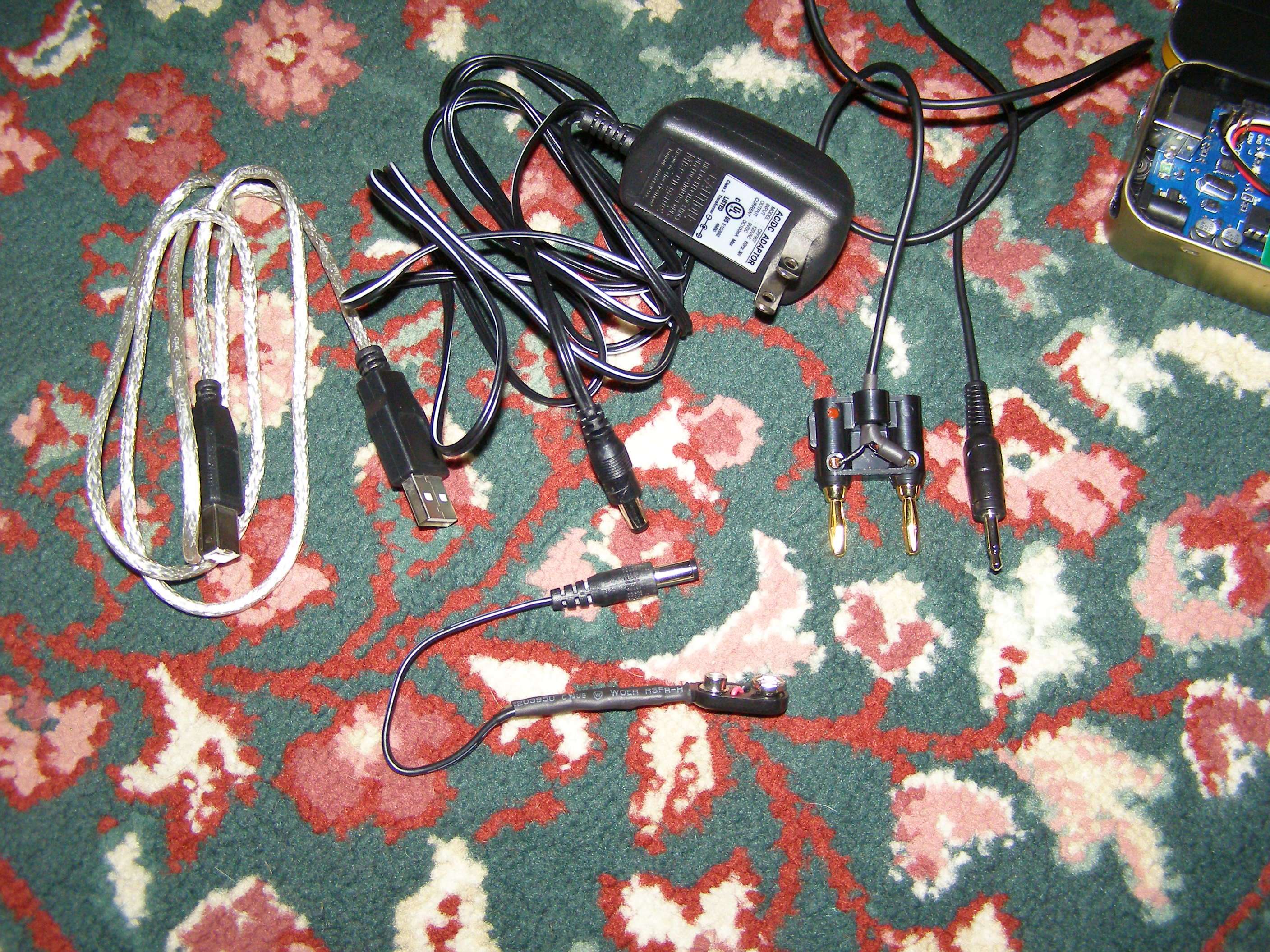
9V wall wart, USB cord, 9V battery connector, 1/8" male to banana plug
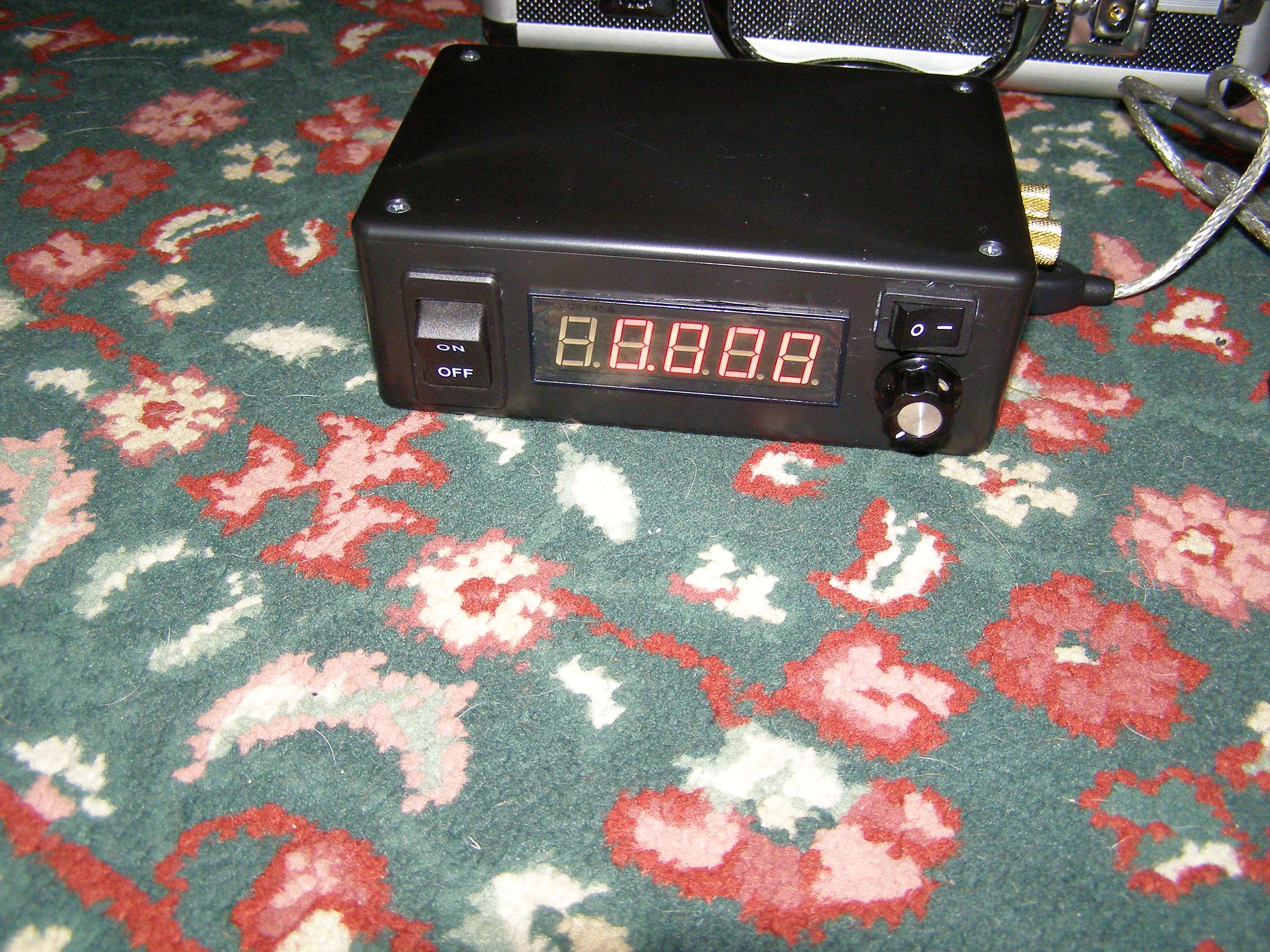
Shown with all connections (box can be open or closed)
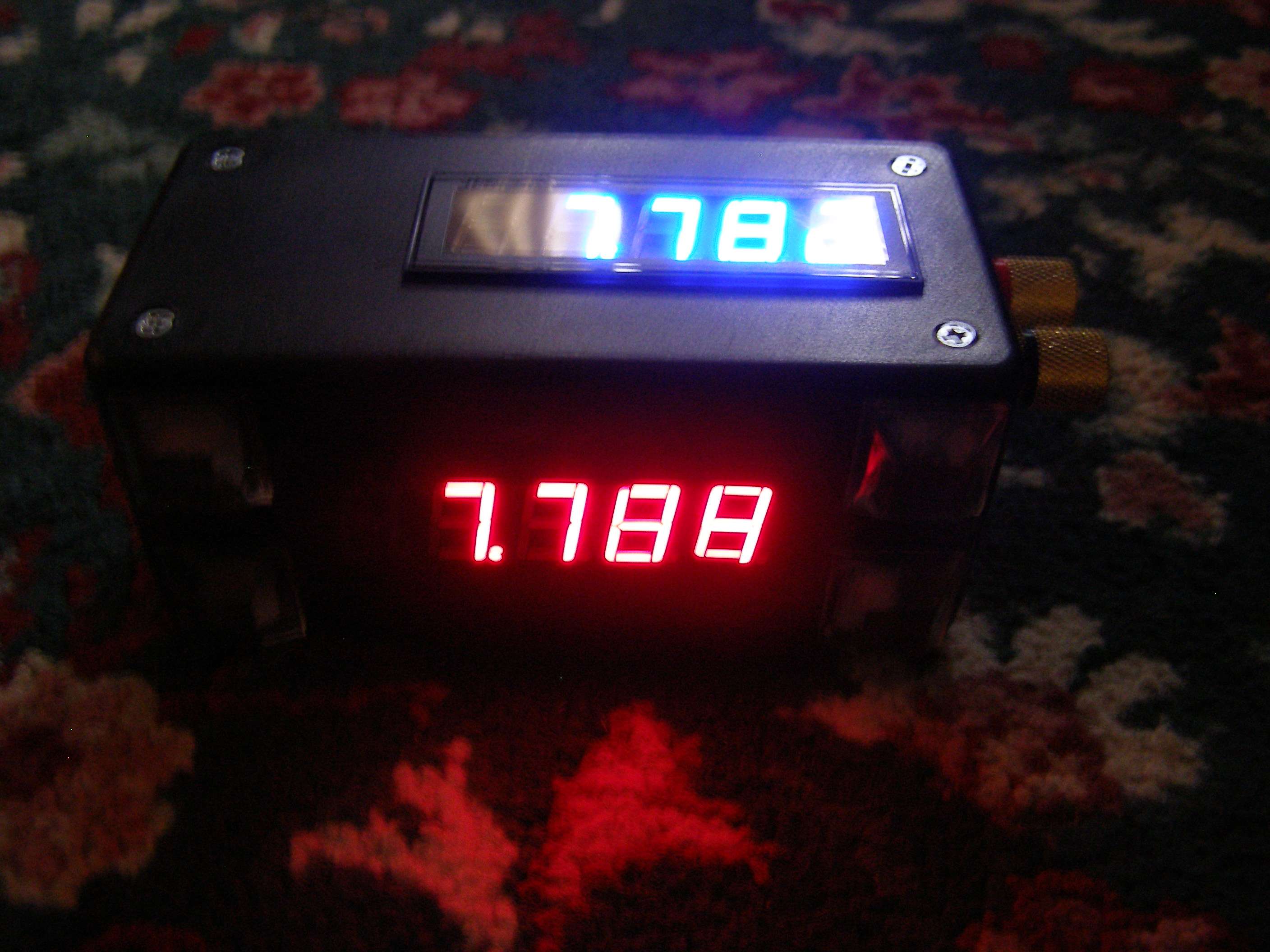
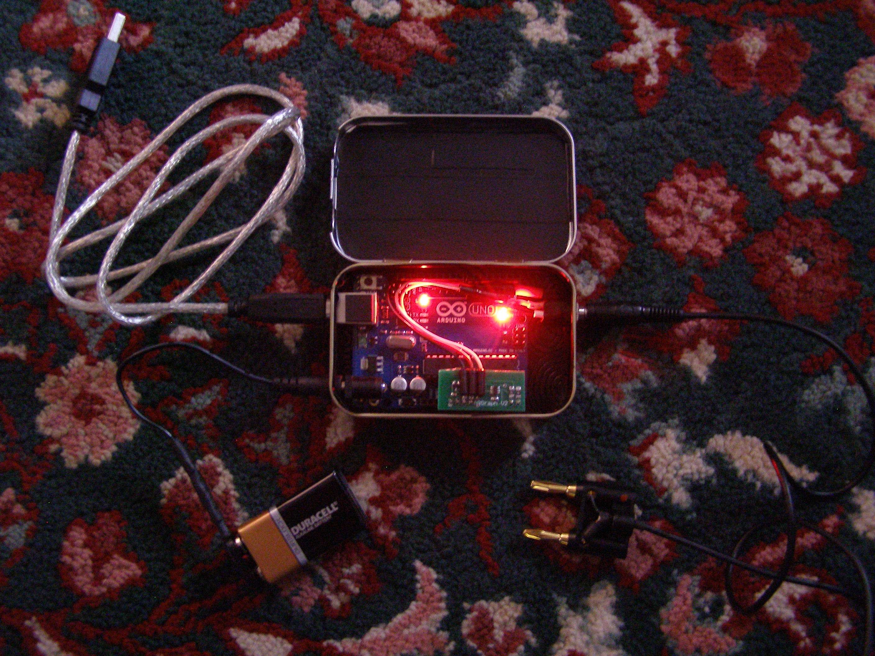
Shown lit up and ready to roll")
Comments:
-You should test your wall warts output as even though mine is labelled 9V, it actually puts out 11.53V.
-Arduino need 7-12V
-Data logging board needs 5.2-12V
-IF you plug in the USB connector with no other power (side connector or Vin pin), it will all work (tested this). You will see about 4.5V between the Vin and ground connections on the data logger. However, ARGLaser said that "at the higher powers it will read inaccurately because the 5V reference will be off. You need voltage above 5.2V to generate an accurate reference". So, unless you are testing low powered lasers, don't use just USB power for everything.
-You can use EITHER the side power input or Vin to power the data logger but NOT :tsk: both at the same time or it will go poof with possible funny smell
-You have to snip the Vin pin if the voltage is too low for the Arduino to run off of. You can apply 7-12V to the Vin without snipping it (such as using the +side of 9V to an Ophir).
-The reason there's not an issue between Vin/side power connector and the USB power is that the Arduino has an auto selector so that when both USB and another source are connected, it will use the other source.
-The only software needed is the Arduino and Peregrine to get everything up and running.
-I had an issue with the Peregrine program not opening on my main computer with the issue being that I just needed to update Java. Program tested on Windows XP desktop, laptop, Vista laptop and Windows 7 netbook all good.
-Install the Arduino software first and follow the procedure to make sure it loads properly and you see it under Ports in device manager with a Com port # and you are good. Don't need to flash anything. Peregrine should then be able to see the com port and you are good to go.
Big :thanks: to all involved in this project especially ARGLaser and Trevor:wave: Please consider supporting these guys with a few $.
Pete
As always with me, this is me messing around and I may change anything at anytime.
I was trying to decide what to do with the data logger to make it somewhat protected and easily hooked up to either of my LPMs. Had originally made both the TEC based and Ophir based LPMs so they could easily be hooked up with alot of options (I'm heavy on options). So these are a few pictures of the units so you can see why I did what I did for the data logger.
Both units have switchable displays and banana plug compatible outputs.
TEC based unit:
Ophir based unit:
This is what I did with the data logger:
Altoids can (don't necessarily have to use this flavor)
Side view showing holes for USB and Power connector
Standard 1/8" mono headphone jack
Insulated and very well fitting box. Very secure
Wires routed out of way of indicator lights (red Vin wire not used)
9V wall wart, USB cord, 9V battery connector, 1/8" male to banana plug
Shown with all connections (box can be open or closed)
Shown lit up and ready to roll
Comments:
-You should test your wall warts output as even though mine is labelled 9V, it actually puts out 11.53V.
-Arduino need 7-12V
-Data logging board needs 5.2-12V
-IF you plug in the USB connector with no other power (side connector or Vin pin), it will all work (tested this). You will see about 4.5V between the Vin and ground connections on the data logger. However, ARGLaser said that "at the higher powers it will read inaccurately because the 5V reference will be off. You need voltage above 5.2V to generate an accurate reference". So, unless you are testing low powered lasers, don't use just USB power for everything.
-You can use EITHER the side power input or Vin to power the data logger but NOT :tsk: both at the same time or it will go poof with possible funny smell
-You have to snip the Vin pin if the voltage is too low for the Arduino to run off of. You can apply 7-12V to the Vin without snipping it (such as using the +side of 9V to an Ophir).
-The reason there's not an issue between Vin/side power connector and the USB power is that the Arduino has an auto selector so that when both USB and another source are connected, it will use the other source.
-The only software needed is the Arduino and Peregrine to get everything up and running.
-I had an issue with the Peregrine program not opening on my main computer with the issue being that I just needed to update Java. Program tested on Windows XP desktop, laptop, Vista laptop and Windows 7 netbook all good.
-Install the Arduino software first and follow the procedure to make sure it loads properly and you see it under Ports in device manager with a Com port # and you are good. Don't need to flash anything. Peregrine should then be able to see the com port and you are good to go.
Big :thanks: to all involved in this project especially ARGLaser and Trevor:wave: Please consider supporting these guys with a few $.
Pete
Last edited: