int lred = 50; // blanking pin red
int lgreen = 46; // blanking pin green
int lblue = 42; // blanking pin blue
int valx = 2040; // set x to center
int valy = 2040; // set y to center
int valxc = 0; // copy of valx for the rotation formula
int valyc = 0; // copy of valy for the rotation formula
int midx = 2040; // master center for x
int midy = 2040; // master center for y
int k = 0; // position in imdata aray
int step = 1; // rotation speed
int zoom = 3; // size of image
int points = 10; // number of points in the image
// image data
int imgdata [250] =
{
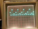
1, 4000, 4000,
1, 0, 0,
1, 4000, 4000,
1, 0, 0,
1, 4000, 4000,
1, 0, 0,
1, 4000, 4000,
1, 0, 0,
1, 4000, 4000,
1, 0, 0,
};
void setup()
{
pinMode(lred, OUTPUT);
pinMode(lgreen, OUTPUT);
pinMode(lblue, OUTPUT);
pinMode(DAC0, OUTPUT);
pinMode(DAC1, OUTPUT);
analogWriteResolution(12);
digitalWrite(lred, LOW); //turn off laser
digitalWrite(lgreen, LOW); //turn off laser
digitalWrite(lblue, LOW); //turn off laser
} // end void setup
void loop()
{ for (k = 0; k < points*3; k++)
{
switch (imgdata[k])
{
case 0:
black();
break;
case 7:
red();
break;
case 2:
green();
break;
case 3:
blue();
break;
case 4:
white();
break;
case 5:
turq();
break;
case 6:
yellow();
break;
case 1:
white();
break;
default:
black(); // just to be safe
}
k = k + 1; //inc counter to index to x coord
valx = imgdata[k]; //pick up the x-coordinate from the image data array
k = k + 1; //inc counter to index to Y coord
valy = imgdata[k]; //pick up the y-coordinate from the image data array
//output x & y co-ord
analogWrite(DAC0, valx); // * zoom + midx);
analogWrite(DAC1, valy); // * zoom + midy);
//delay(1); // pauses for xx miliseconds
//delayMicroseconds(500); // pauses for xx microseconds
}
} // end void loop
//(x,y)---->(x*Cos(°)-y*Sin(°), x*Sin(°)+y*Cos(°)
void black() // color 0
{
digitalWrite(lred, LOW);
digitalWrite(lgreen, LOW);
digitalWrite(lblue, LOW);
}
void red() // color 1
{
digitalWrite(lred, HIGH);
digitalWrite(lgreen, LOW);
digitalWrite(lblue, LOW);
}
void green() // color 2
{
digitalWrite(lred, LOW);
digitalWrite(lgreen, HIGH);
digitalWrite(lblue, LOW);
}
void blue() // color 3
{
digitalWrite(lred, LOW);
digitalWrite(lgreen, LOW);
digitalWrite(lblue, HIGH);
}
void white() // color 4
{
digitalWrite(lred, HIGH);
digitalWrite(lgreen, HIGH);
digitalWrite(lblue, HIGH);
}
void turq() // color 5
{
digitalWrite(lred, LOW);
digitalWrite(lgreen, HIGH);
digitalWrite(lblue, HIGH);
}
void yellow() // color 6
{
digitalWrite(lred, HIGH);
digitalWrite(lgreen, HIGH);
digitalWrite(lblue, LOW);
}
void lila() // color 7
{
digitalWrite(lred, HIGH);
digitalWrite(lgreen, LOW);
digitalWrite(lblue, HIGH);
}


")


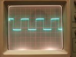
") . Solid as a rock.
. Solid as a rock.
 :beer: