Welcome to Laser Pointer Forums - discuss green laser pointers, blue laser pointers, and all types of lasers

Buy Site Supporter Role (remove some ads) | LPF Donations

Links below open in new window

FrozenGate by Avery

ARDUINO & DAC for XY projector

@ OldNo7

Which DAC will you use?

If you cannot update them simultaniously, it will not work.
Then you are back at post 1 of this thread.;)


I also tried the MCP4922 DAC and applied the LDAC function. (See post#45)

It worked but way, waaaaayyyy too slow.

I haven't looked into any specific DACs yet. This thread has just started me thinking about it.

If the micro has 2 ports that are sequentially mapped in memory you could write to them simultaneously by using a pointer that's 2x the size of 1 port.
For example if p1 is at 0x0000 and p2 is at 0x0008 you can write to both ports using a int16 pointer to 0x0000

BionicBadger does that sound right?

I don't mean to through the conversation off topic I just really like the idea. It seems like at that point the limiting factor would probably be the DAC.


While memory-mapped DAC IO would work, it probably won't make much difference if the DACs are on the chip. The DAC calls are probably non-blocking, in other words they return immediately after setting their registers, and then the conversion takes place in the background. On the Cortex M3 that the Arduino Due uses, it also takes care of refreshing the DAC values as needed.

Even if the calls are blocking, the conversion time is on the order of 1Mhz, so it won't much difference to the slow point-speeds needed for galvos. The per-channel DAC operations on the ATmega/I2C were so noticeable because the I2C bus is really slow. For on-chip DACs, even the Arduino's PWM "DAC"s it would probably be substantially faster.
 
I ment to for using an external DAC and the less powerful Arduino. Like the setup in the begining of this thread. I don't think it'd be a replacement for what camvo has now, I just thought it might be a fun exercise and should be much faster than the I2C or SPI.

@camvo This looks like it's probably the ilda test pattern already converted to bytes.
https://github.com/j4cbo/j4cDAC/blob/1df958ea396047f6fc70513dde6b7e56e6c88973/firmware/old/ildatest.c

It's 6 bytes per point (see pattern.c in the same directory).
Code:
unsigned int16 x,y,r,g,b;

while(1)
{
	int i=0;
	while ((i+6) < sizeof(ildatest_bts)) 
	{
		x = ((ildatest_bts[i + 3] << 8) & 0xF000)  | (ildatest_bts[i + 4] << 4);
		y = ((ildatest_bts[i + 3] << 12) & 0xF000) | (ildatest_bts[i + 5] << 4);
		r = ildatest_bts[i +0] << 4;
		g = ildatest_bts[i +1] << 4;
		b = ildatest_bts[i +2] << 4;
		//printf("%d,%d 0x%x 0x%x 0x%x\n", x,y,r,g,b);
		if (r > 0)
			red();
		else 
			black();

		analogWrite(DAC1, x);
		analogWrite(DAC0, y);
		i+=6;
	}
}
 
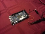
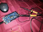
I just did a test with the scope.

I used the below code.

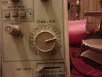
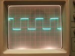
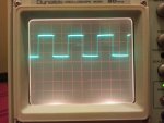
To put out one complete cycle (max and min), it needed 3 time devisions of 10 µsec so 30 µsec.

In this 30 µsec 2 points were sent from the DAC.
So it takes 15 µsec to write one value.

That means it can write 66,667 values per second???
(I wonder how much a 60k scanner costs!)


I put color 1 as last in the switch case row to make it evaluate every case.
I also put color 1 as first in the switch case.
I could not measure any difference in the blanking.

I also could not measure the return to the beginning of the data array.

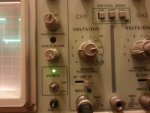
I am a bit puzzled but the output voltage though. (VOLTS-CALIBRATED.jpg)
It seems to be between 0.6 and 2.8 volts. (Huh??)

Code:
int lred      = 50;    // blanking pin red
int lgreen    = 46;    // blanking pin green
int lblue     = 42;    // blanking pin blue

int valx     = 2040;   // set x to center
int valy     = 2040;   // set y to center
int valxc    = 0;      // copy of valx for the rotation formula
int valyc    = 0;      // copy of valy for the rotation formula
int midx     = 2040;   // master center for x
int midy     = 2040;   // master center for y

int k        = 0;      // position in imdata aray
int step     = 1;      // rotation speed
int zoom     = 3;      // size of image

int points   = 10;      // number of points in the image

// image data
int imgdata [250] =
    {
     1,   4000,   4000,	   
     1,      0,      0,
     1,   4000,   4000,	   
     1,      0,      0,
     1,   4000,   4000,	   
     1,      0,      0,
     1,   4000,   4000,	   
     1,      0,      0,
     1,   4000,   4000,	   
     1,      0,      0,
    };
 
void setup()   

{                
 pinMode(lred,   OUTPUT);
 pinMode(lgreen, OUTPUT); 
 pinMode(lblue,  OUTPUT);
 
 pinMode(DAC0,  OUTPUT); 
 pinMode(DAC1,  OUTPUT); 
 
 analogWriteResolution(12);  
 digitalWrite(lred,   LOW);    //turn off laser
 digitalWrite(lgreen, LOW);    //turn off laser
 digitalWrite(lblue,  LOW);    //turn off laser
} // end void setup

void loop() 
{      for (k = 0; k < points*3; k++)  
          {   
           switch (imgdata[k]) 
             {
              case 0:
                black();
                break;
              case 7:
                red();
                break;
              case 2:
                green();
                break;
              case 3:
                blue();
                break;
              case 4:
                white();
                break;
              case 5:
                turq();
                break;
              case 6:
                yellow();
                break;
              case 1:
                white();
                break;
              default: 
                black(); // just to be safe    
             }

          k = k + 1;                          //inc counter to index to x coord
          valx  = imgdata[k];                 //pick up the x-coordinate from the image data array
          k = k + 1;                          //inc counter to index to Y coord
          valy  = imgdata[k];                 //pick up the y-coordinate from the image data array
 
      
          //output x & y co-ord
          analogWrite(DAC0, valx); // * zoom + midx);
          analogWrite(DAC1, valy); // * zoom + midy);  

          //delay(1);                        // pauses for xx miliseconds
          //delayMicroseconds(500);        // pauses for xx microseconds  
         }     
       
} // end void loop

//(x,y)---->(x*Cos(°)-y*Sin(°), x*Sin(°)+y*Cos(°)

void black()  // color 0
{
 digitalWrite(lred,   LOW);
 digitalWrite(lgreen, LOW);
 digitalWrite(lblue,  LOW);  
}

void red()    // color 1
{
 digitalWrite(lred,   HIGH);
 digitalWrite(lgreen,  LOW);
 digitalWrite(lblue,   LOW);
} 
 
void green()  // color 2  
{
 digitalWrite(lred,    LOW);
 digitalWrite(lgreen, HIGH);
 digitalWrite(lblue,   LOW);
}

void blue()   // color 3
{
 digitalWrite(lred,    LOW);
 digitalWrite(lgreen,  LOW);
 digitalWrite(lblue,  HIGH);
}

void white()  // color 4
{
 digitalWrite(lred,   HIGH);
 digitalWrite(lgreen, HIGH);
 digitalWrite(lblue,  HIGH);
}

void turq()   // color 5
{
 digitalWrite(lred,    LOW);
 digitalWrite(lgreen, HIGH);
 digitalWrite(lblue,  HIGH);
}

void yellow() // color 6 
{
 digitalWrite(lred,   HIGH);
 digitalWrite(lgreen, HIGH);
 digitalWrite(lblue,   LOW);
}

void lila()   // color 7
{
 digitalWrite(lred,   HIGH);
 digitalWrite(lgreen,  LOW);
 digitalWrite(lblue,  HIGH);
}
 

Attachments

  • SETUP.jpg
    SETUP.jpg
    365.6 KB · Views: 408
  • VOLTS.jpg
    VOLTS.jpg
    338.7 KB · Views: 314
  • TIME.jpg
    TIME.jpg
    339.9 KB · Views: 277
  • WAVE.jpg
    WAVE.jpg
    391.2 KB · Views: 320
  • VOLTS-CALIBRATED.jpg
    VOLTS-CALIBRATED.jpg
    388.8 KB · Views: 246
Want to take the oportunity to thank my buddy Jos Schluter who was so kind to borrow me his scope. (For 3 months now!!)

Thanks Jos!!
 
Last edited:
I will put the Ilda test frame through the scope tomorrow to see what happens.

A pitty the scope cannot be blanked......
 
Did some more testing today.

To make sure that I am realy measuring the DAC output, I varied the values in order to see if it realy changed.

I changed the image data to less points in the array and different values to see where you are in the array.
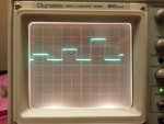
The graph for x and y was exactly the same! (10 µsec per time devision)

Now I could measure the delay of returning to the beginning of the array.
I could not measure that difference yesterday because of too many points and I did now where to look.
Notice that after the 3rd and highest cycle, the time at the lower voltage is slightly longer than the others.
I think this is the time to return to the beginning. It does make sense....


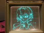
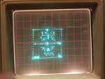
Further I ran the ILDA test image through the scope Bionic-Badger.
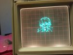
The image stood like a rock. No vibration in the points. It was as still as you are looking at the image.

Same for the Yoki girl (Multimode :yh:). Solid as a rock.

This all is evidence that you could/should use much faster scanners than my 20kpps scanners on the arduino DUE.


Code:
int points   = 6;      // number of points in the image

// image data
int imgdata [250] =
    {
     1,   1000,   1000,	   
     1,      0,      0,
     1,   2000,   2000,	   
     1,      0,      0,
     1,   4000,   4000,	   
     1,      0,      0,
    };
 

Attachments

  • SPEED TEST-2.jpg
    SPEED TEST-2.jpg
    338.9 KB · Views: 506
  • SETUP-2.jpg
    SETUP-2.jpg
    503.1 KB · Views: 399
  • YOKI SMALL.jpg
    YOKI SMALL.jpg
    400.8 KB · Views: 2,306
  • YOKI LARGE.jpg
    YOKI LARGE.jpg
    435.1 KB · Views: 591
  • ILDA TEST SCOPE.jpg
    ILDA TEST SCOPE.jpg
    389.6 KB · Views: 2,680
Last edited:
Hi canvo,

Looks good,

With the 328 I was getting a lot of flicker with Yoki girl - do you know the time it take for one complete scan of the point table?

ATB
MM
 
From the first (and second) speed test the conclusion is:
it takes 15 µsec to write one value.


The Yoki girl image has 1680 points.

1680 x 0.000015 sec = 0.0252 sec

That means 39.7 Hz refresh rate for the entire image.

This is what the Arduino DUE can output, without any delay commands.

Then it depends on the scanner speed how much delay you have to build into the code in order to give the scanners time to catch up with the arduino.
 
Wonderful data. Nice work.

If it takes 15us to write one value, it could take 30us to write both the X & Y values. With no blanking, that looks like 1 / 0.00003us = 33K points per second. Not too shabby.

I see by the code in post #116 the blanking (laser control) values are written regardless if they change. I wonder how much delay these incur. I wonder how many cycles per second your for-next loop can run. I think that's the real test.

Another idea to benchmark is to keep a counter in memory, and increment it each time through the loop (X, Y and 3 blanking values written.) Then, every 1000 or 10,000 cycles, toggle one of the output pins, and measure the time interval of the output with your scope. Divide it out, and that should tell us the maximum speed this setup can drive a projector.

I can see it's likely a setup like this may drive 12K scanners to their limits, which is pretty decent for a DIY setup.

If Yoki Girl has 1680 points, isn't that 3360 X & Y values? 3360 writes? With no blanking, at 33Kps, that looks to be about 9Hz, which could explain the flicker.

While I cannot speak for the Arduino compiler specifically, most of the compilers I use optimize the code. As such, you may find things like switch() are optimized and not compiled the way it's written. Meaning, writing case 1 at the end of your switch may not mean that's where it's compiled.

This is a great thread, and I am very interested in your work. Thank you for sharing.
 
Wonderful data. Nice work.

If it takes 15us to write one value, it could take 30us to write both the X & Y values. With no blanking, that looks like 1 / 0.00003us = 33K points per second. Not too shabby.
I can see it's likely a setup like this may drive 12K scanners to their limits, which is pretty decent for a DIY setup.
If Yoki Girl has 1680 points, isn't that 3360 X & Y values? 3360 writes? With no blanking, at 33Kps, that looks to be about 9Hz, which could explain the flicker.

Hi,

I think a "value" is a co-ordinate pair? - Canvo will be able to confirm.

I was getting 10hz refresh using Yoki girl and that was using a 16Mhz ATMega328 + SPI DAC - so I'm sure the Due is banging out the data a lot faster ;-)

ATB
MM
 
With value, I mean a point with a color at location x,y.
Yoki has 1680 lines in the data array with color and x,y coordinates.


The code is the same code which does the Yoki girl and the ILDA TEST frame.
For the test, I just put in 6 lines of data in the array with color, x and y.
I deleted the delay commands.

The code picks up the data from the array: color, X and Y.
The code actually writes the color and both values, x and y.

I only measured the X DAC.
But in the meantime, the y value and color are written too.
(The scope cannot display x and y at the same time. It has only 1 electron cannon.)

So to my opinion, color, X and Y are written in 15µsec.
Giving a refresh rate of 66.6k

But....... to be sure, I will set up the scope once more and modify the code and let it write only the X coordinate and no color and see what happens.
I will also shoot a video of Yoki so you can see how stable the image is.


@ NultiNode: Hey, the name is camvo not canvo. :D :beer:
.
 
Last edited:
Hi Guys,


I hooked the Arduino up to the scope.

I stripped the code to an absulute minimum. (See below)
The code now picks up a value and writes it to the dac, picks up next value, etc.
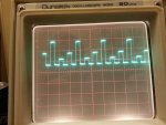
Have a look at the scope image. (10 µsec per time devision)

The speed is a whopping 5 µsec for writing 1 value to the DAC!!

So 15 µsec to digitalWrite a color, and write x and y to the dacs is correct.
This give us a refresh rate of 66.6 Kpps.

I hope you are convinced now pschlosser.
Is this the benchmark you were talking about Bionic-Basher?

I also took a video of the Yoki girl. There are no delay commands in code.
Just look how beautiful and stable the image is.

I have got to get faster scanners!!!


Code:
int valx     = 0;      
int k        = 0;      // position in imdata aray
int points   = 6;      // number of points in the image
// image data
int imgdata [250] =
    {
     1000, 0 , 2000, 0, 4000, 0,
    };
 
void setup()   
{                
 pinMode(DAC0,  OUTPUT); 
 analogWriteResolution(12);  
} 

void loop() 
{     
  for (k = 0; k < points; k++) 
      {
       valx  = imgdata[k];    //pick up the x-coordinate from image data array
       analogWrite(DAC0, valx); 
      }
}
 

Attachments

  • SPEED TEST-SINGLE CHANNEL-BARE MINIMUM.jpg
    SPEED TEST-SINGLE CHANNEL-BARE MINIMUM.jpg
    377.8 KB · Views: 478
  • YOKI STABILITY SCOPE.wmv
    YOKI STABILITY SCOPE.wmv
    7.5 MB · Views: 158
Hi, just found this thread and I'm looking to drive a 30k rgb ilda from a Arduino Due

Camvo - the shield design you posted will this drive an ilda projector ? If so any chance of posting a schematic as I would like to mock it up on some breadboard first before etching a pcb , also I would want to stack it up with an Ethernet shield. Cheers

Henny
 
Hi Henny,

Basically all you have to do is to route the blanking signals for RGB and the signals XY from the correction amplifiers to an ILDA connector and you are done.
Do not forget to make the interlock connection on the ILDA connector.


Back
Top