Welcome to Laser Pointer Forums - discuss green laser pointers, blue laser pointers, and all types of lasers

Buy Site Supporter Role (remove some ads) | LPF Donations

Links below open in new window

FrozenGate by Avery

Anyone know the power of DVD Reader LDs?

Benm said:
For the aixiz module, i'd say the focal point is roughly 1 cm (100d), and the diameter of the lens is 6 mm or so. Most laser diodes have a beam less than a radian wide (usually  more like 30 degrees or so), so it works out okay.

Thanks for the info!

From my experimenting it seems my lens is good enough as it is.. The only problem is positioning it perfectly for max output..

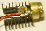
I'm nearing completion of my Phaser.. I glued two IC heatsinks to the LDs chunk of metal. Now i'll glue the lens assembly (brass) to the heatsinks (for even more heat dissipation).

The housing is complete, and so is the driver.. I'll be using a 260mAh hobby grade LiPo as a power source..

I'll post the pics as the work progresses...


What do you use to glue them anyways, something thermally conductive?
 
Benm said:
What do you use to glue them anyways, something thermally conductive?

I use the same glue i used on my helicopter motors that were constantly overheating...

Just plain old CA. I'm also using the same IC heatsinks.. On the motors i just had to bend them first for them to hug the motor nicely..

And while some special thermal conductive glue might be a little bit better, CA works amazingly well. My motors went from scorching hot to barely warm.. (Before this they were too hot to touch.. They would burn my fingers..)


You just have to put some tape over the LDs lense opening while the glue is curing, so the CA's vapors wouldn't destroy it..

In my initial experiments the LD didn't go over 33 degrees centigrade with this setup. (Measured with a non contact IR thermometer)


EDIT: Of course, while glueing, you have to press it together very strong, to make the glue layer extremely thin (if you make the surfaces totaly flat first, that is).. The thinner, the better. This way the thermal conductivity of the glue itself probbably matters much less.

I'll attach a pic in a moment..
 
Well, the moment took longer than i first thought, since it was hard to get the lense holder positioned perfectly...

Here's a pic of the LD glued to some IC heatsinks and the adjustable collimator housing on top..

Everything improvised, but i hope it works out ok in the end..
 

Attachments

  • LD_heatsinks_and_the_lens_housing.JPG
    LD_heatsinks_and_the_lens_housing.JPG
    28.3 KB · Views: 183
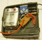
And a pic of a part of the Phaser enclosure.

There's a small FullRiver LiPo, a switch and a very simple LD protection circuitry.. I had to solder the components together without a board, since it wouldn't fit otherwise.. The switch is positioned in such a weird angle, cos the enclosure had a hole there for a button..

It takes away a lot of place this way, but it'll work...
 

Attachments

  • Laser_enclosure.JPG
    Laser_enclosure.JPG
    44.6 KB · Views: 171
Nice the way you improvised everything...I hope it all works out ok. And you are making good use of a LiPo battery too.. ;D
 
Gazoo said:
Nice the way you improvised everything...I hope it all works out ok. And you are making good use of a LiPo battery too.. ;D

And i'm glad the stupid helicopter is finally put to some use - donating internal organs..

The brushes from the motor are going onto a better heli, since they're carbon and the ones in the other heli keep dying.. (wearing out)

In the end not much will be left of it.. ;)
 
I hear ya, I went brushless with my helis for the same reason. ;)
 
Gazoo said:
I hear ya, I went brushless with my helis for the same reason.  ;)

Oh i see.. So you're also a heli addict? Hehe.. Nice..

I just noticed i'm talking with you on two different forums at the same time, assuming it's someone else.. :)
 
I just managed to finish the final step - glueing the lense assembly in the right place... (in the pic above it was just put there to show how it's gonna be done)

After the glue dries, it's just a minute of soldering, before i have a working laser "pointer". A burning laser pointer that is.. ;)


BTW: Where do you guys order your AixiZ modules from? DealExtreeme or AixiZ directly?

I ordered from the AixiZ site directly, but haven't gotten any response from them after making the payment...
 
I just figured out, i can use the original heli's LiPo charger to charge this battery even tho i wired it in parallel.

Since i'm using half of the LiPo's protection circuitry, i can also use half of the charger.. The charging process will be slower, since the capacity is now double, but this will make the battery last longer.

Now i can even mount the heli's plug directly into the housing and just plug the charger in when needed..

This is great! Soon there won't be much left of that low quality heli anymore..
 
IgorT said:
[quote author=MarioMaster link=1193387877/15#22 date=1193511509]it was running at about 60ma from i think 3 volts or so, i would run at like 50ma for better diode life though since any higher than 60ma made it mode hop, and i was running it from my home built power supply which uses 4 LM317 regulators in parallel


Thanks for the info!

What kind of housing is that in your pic and where did you get that "heatsink" block?
Are you using four LM317 in parallel cos they are the small ones (100mA max) or are they the bigger version?


BTW: What is "mode hop"?[/quote]

the diode housing i pulled from a laser printer, the heatsink was all part of it. the LM317s in my psu are the big version, this supply usually runs things larger than a laser diode ;)
 
MarioMaster said:
the diode housing i pulled from a laser printer, the heatsink was all part of it. the LM317s in my psu are the big version, this supply usually runs things larger than a laser diode  ;)

I see.. Now you just have to tell me what mode hop is and i'll know everything i wanted to.. :)
 
BTW: Glue dried, everything soldered, fits perfectly.. It's actually amazing how well it fits since if the battery was any bigger i couldn't put it in this small enclosure.. (74x44x18mm)..

And if i drive the LD at 260mA, the battery would last for one hour of continuous use.. Not that i would ever leave it on for that long..

Now i just have to set the current and i'm done.. Yay! ;)

Damn! I finished it, set the current to 200mA and tested it, only to discover the lense is too close to the LD... I must have made a mistake in my calculations..

If i don't manage to make a deep enough indentation into the part that pushes the lense in, i will have to take everything apart.. The LD, the heatsinks and the lenseholder that are all glued together... :(


UPDATE: I noticed the convex side of the lense has an edge.. I removed this edge and it was enough, that i can now get a narrow laser beam..

My "Phaser" WORKS!!!!

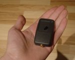
Finally a working portable and very powerfull laser.. I'm happy right now... I'm attaching a pic so you can see how small it is...
 

Attachments

  • Finished_Phaser.JPG
    Finished_Phaser.JPG
    46.4 KB · Views: 141
Nice job! You seem to be good with glue, the whole assembly with the 2 DIP heatsinks looks very nice.

Personally i prefer metal enclosures since they deal with the heat better by spreading it outwards, but if this suffices i think this form factor is very nice.
 
Benm said:
Nice job! You seem to be good with glue, the whole assembly with the 2 DIP heatsinks looks very nice.

Personally i prefer metal enclosures since they deal with the heat better by spreading it outwards, but if this suffices i think this form factor is very nice.

Thanks! I really like this shape. It's very small for something this powerfull..

Actually i was even considering adding a tiny Peltier TEC under the LD and mount it through the plastic enclosure with a larger heatsink outside... This way i could drive it much harder.. It already did 280mA with no problem when mounted directly on a larger heatsink.. So with a TEC i wouldn't worry about putting 300 or maybe even 350mA through it..

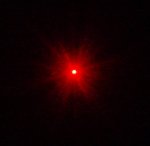
But with the current optics i get this weird spread pattern on the wall... I'll post a pic, so you can tell me if it's normal. BTW: In the pic the spread pattern looks MUCH smaller than it actually is..
 

Attachments

  • Spread_pattern.JPG
    Spread_pattern.JPG
    12.7 KB · Views: 149


Back
Top