Welcome to Laser Pointer Forums - discuss green laser pointers, blue laser pointers, and all types of lasers

Buy Site Supporter Role (remove some ads) | LPF Donations

Links below open in new window

FrozenGate by Avery

9mm 808nm + crystal and no green?

dig-cams are a very good method, and that's what I recommend. If you're working with lower powered 808nm diodes (up to about 200mW) you can use your eyes as long as you watch your angles so as not to reflect the IR directly into your eyes. 808nm is close enough to visible for there to be a faint red glow that will help you align everything. Using your eyes is risky, so I personally recommend using an IR sensitive camera any time you work with IR.


Your best bet is to use a simple collimating lens to focus the 808 (assuming your diode is 808 with a low tolerance) to a point just past the input surface of your crystals. Direct-coupling (placing the diode right next to the crystals) does work, but it's easier and more efficient if the 808nm light is focused into the crystals.

Most of lenses have focal point of 5mm (aixiz) or more.
If he wants to focus light with lens he has to put lens much more than 5mm away from diode so he can have focal point at the closest distance possible.
That means that he need much longer module and may not fit easily in host.
Another problem is that 7mm lenses with 5+mm FL can not collect all light from IR multimode diodes.

The best way is to remove can from diode so he can put crystal closer to diode.
 
Direct coupling is inefficient, plain and simple. In good portables, the diode is always collimated (at least with a FAC) to channel the pump energy into the crystal. In real good DPSS lab-style laser, a pair of prisms is used along with the FAC to even out the pump energy. Direct-coupling is half-assed, but if that's the only way it'll work in your installation, that's all you can do.

Here's where I'm coming from: I believe that if you intend to learn how to construct DPSS lasers, you should learn the proper way, so any time I give advice it is with that in mind. Cheap Chinese lasers use direct-coupling all the time, but to me that's a big reason why I consider them to be inferior. Proper focusing and correction of the pump energy is the only good way to do it if efficiency, stability and beam quality are important to you.
 
Last edited:
Columinating before the crystal is done with exterior lenses or an FAC coating on the diode normally.
HMike

Four things:
1. It's "collimating."
2. The diode's IR beam is never collimated in a green, but it can be focused on the crystal face.
3. FAC can not be achieved with a coating, it must be a lens.
4. FAC does not collimate, it brings the fast-axis divergence closer to the slow axis divergence.
 
Wow, alot of help and information.

For now i dont build a DPSS Laby. Many thanx for the explanation.
I want to go with the housing i have already. Like i understand for that reason i can cancel focusing the ir bevor the crystal. It take to much lenght.

The hottest topic for me is the decan thing...

How is this done best way? On a lathe?
Any hints?


@HIMNL9
I hope the surface of the crystal is clean, i keep an eye on that topic.


@all
I use my mobil phone camera of my samsung I550 it shows the ir.
My DSLR cannot catch the ir maybe a filter somewhere.


Thanx


Daniel
 
Juhu, it works.

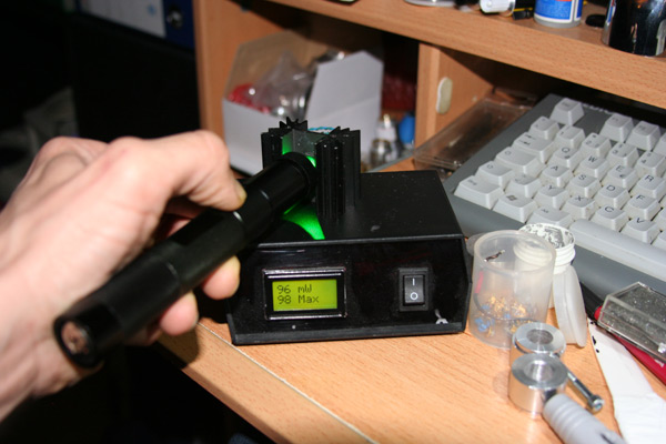
I decan the 9mm diode and now the output is best at 90 mw green from 350 mw IR.

Complete with the driver at 800ma to the driver i get 130 mw of green beam.


Very nice, crystal closer to the diode is the solution.


I take some pictures, i post later.


Thanx

Daniel
 
Hm In the end i get only around 100mw green beam.

The 130mw was bevor the two lenses.

working1.jpg


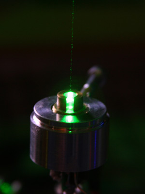
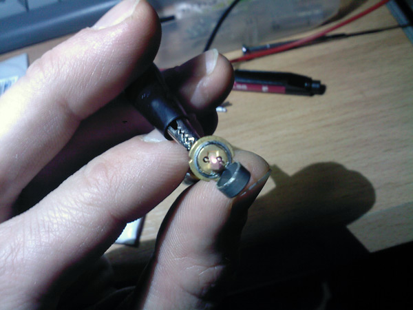
Finally i decan the 9mm diode the brings the distance between the diode and the crystal down to half a millimeter.
The decanning is done with a tomato knife, a make a cut around the can, then carefully break the can of with a pliers. I practice befor with a dead red 5,6mm... ;)

working.jpg


working3.jpg


working4.jpg


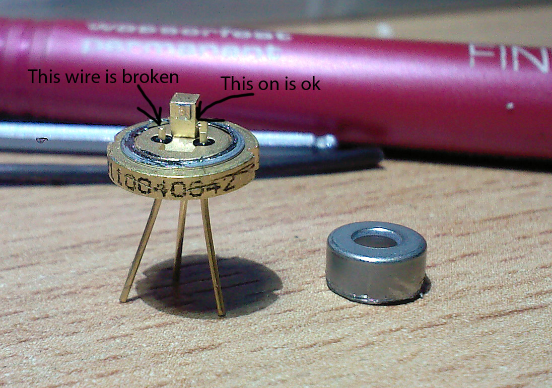
On the diode are 3 connectors.
The anode and cathode is ok, but in the decan prozess I kill the bond wire to the third connector.

I check the output and the output is still the same power like with the undamaged bondwire.
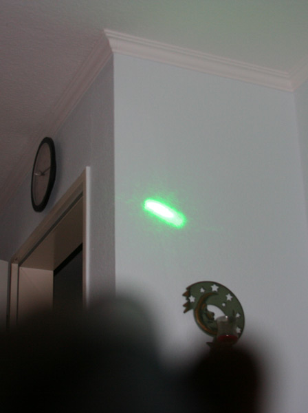
But the beamshap is crap, it looks like it work in tem01 permanently.

working2.jpg


Is this from the defekt bond wire?
The beam can be collimated to infinity with the optics, its just for the photo opened beam.

Some of the picts are from mobile phone because of their capability, one from dslr without the ir radiation.

Best regards

Daniel
 
No, you do not have a broken wire, there, be sure ..... the third pin is sometimes used, in some diodes, for connect a photodiode that rest on the "facet" that you see rear the chip support ..... but in most of these diodes, this chip is not present, so there's just no wire soldered on this pin.

It look that your diode is one without a photodiode (at least from that angle of view), so the pin is just not connected to anything, but also in case the photodiode was there, if the circuit is not using it, you don't need to connect anything on that pin (can be a different hing in those drivers that use the photodiode for a loopback power control, but this depend from your driver) ..... i cannot be 100% sure about this, but from the pics that you have posted, also if your original diode had the photodiode hip (the small square black chip on the base of the diode, rear the laser chip), your driver seem one of the ones that don't need/use the internal photodiode, but one of these that have a big resistor for measure the current and regulate it, so this thing is probably ok ;)

About the dot shape, i'm not sure, can be alignment problems (not just the crystal need to be rotated for match the polarization, but also need to be aligned with the more possible precision for be in center with the laser chip) ..... another possibility is that the diode is so much "multimode", that also the crystal cannot align its output correctly, but in this case, there's not too much to do .....
 
I check the output and the output is still the same power like with the undamaged bondwire.
But the beamshap is crap, it looks like it work in tem01 permanently.

working2.jpg


Is this from the defekt bond wire?
The beam can be collimated to infinity with the optics, its just for the photo opened beam.

Some of the picts are from mobile phone because of their capability, one from dslr without the ir radiation.

Best regards

Daniel

About the dot shape, i'm not sure, can be alignment problems (not just the crystal need to be rotated for match the polarization, but also need to be aligned with the more possible precision for be in center with the laser chip) ..... another possibility is that the diode is so much "multimode", that also the crystal cannot align its output correctly, but in this case, there's not too much to do .....

^There's your answer, Danjoo, and HIMNL9 is likely correct on both counts. As I had posted earlier, using pump correction optics instead of direct-coupling is better if stability, beam quality, and efficiency are important to you. Now you're seeing why.

If building DPSS lasers is interestign to you and you want to learn more about how to do it properly, check out this link: Sam's Laser FAQ - Home-Built Diode Pumped Solid State (DPSS) Laser
 
Last edited:
Many thanks for this clearifying.

Ok the beam has that bad tem01 shape in every power level right from when i turn the power on my lab power supply slowly up. This is permanent. Not mod hopping.


Ok THIS projekt is finished.

But now my blood is stird up for the DPSS thing...

I have a few broken cheap pointers to harvest and some 500mw 808 diodes left.

Seeya later I have to build a green DPSS Labby.
(Accidently iam not at work, and cannot use mashines, because of I take some Parent time for my first son. It will be a getto dremel Labby.) hehe

Many Thanx for your support

Daniel


Back
Top