Welcome to Laser Pointer Forums - discuss green laser pointers, blue laser pointers, and all types of lasers

LPF Donation via Stripe | LPF Donation - Other Methods

Links below open in new window

ArcticMyst Security by Avery

808nm "lethal" supply

dzrick

0
Joined
Nov 7, 2013
Messages
23
Points
3
Hey there, my first post into trying to show something productive!! :)

Well, I've recently purchased a bar diode, it has about 60W peak power, don't worry, until my safety glasses arrive I will only blow up a few load resistors trying to build this "thing" aka PSU to power it. :drool:

The idea

The main concept idea is to use a PC PSU 3.3v rail our 5v rail, I'm a bit confused yet because I don't know how much the voltage will drop when I plug the bar/tec/water cooling to the supply and also don't know if the supply will handle it.. yet my 5V rail can go to about 40Amps...

Quick Circuit description:

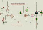
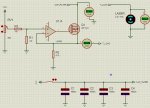
Ok, now assuming that SMPS have "frequency issues", I was going for a capacitor bank on the beginning to avoid spikes and to do further filtering due to high amperage drain, wich without those the waveform would later ripple and of course, cause spikes that could damage my load (or the PSU itself).

The next stage should then be followed by a Variable Constant Current "external" controller, I would be controlling the current needed externally.

Depending on the diode temperature, we will assume that the current and resistance of the laser remains the same, therefore voltage will vary according to the diode's needs.

I would also need a way to monitor the output voltage of the supply to make sure it wouldn't exceed 2.2V, wich is the maximum operation rating of the Laser diode

Conception

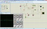
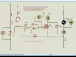
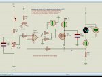
Well, I've "quick-drawn" a circuit, and I've also been reading a lot about circuits using LM317 but I wanted to use an op-amp and a transistor (or transistors in paralell) since it seems to me to be more reliable and of course, cheap. Btw, I'm no electronics guru.... :)

(this circuit was based on successive google searches and readouts).

Pleas check it out, any critics are welcome, I am willing to finish this and hopefully learn a bit more!!!

Regards to all!
 

Attachments

  • fonte_laser.jpg
    fonte_laser.jpg
    299.2 KB · Views: 1,912
Last edited:


Joined
Jul 4, 2012
Messages
2,834
Points
63
Good luck with your build! What is the purpose of said build, however? CNC type purpose, or just a general death ray? Understand the beams on these are pretty ugly, and wont be terribly easy to work with seeing as its IR.

I was going to get a 80W bar a while back to use in a 532 DPSS build, had the crystals picked out that could withstand the heat and everything. But I realized that powering it would be kind of a pain, as it draws a lot of amps and pretty low voltage. So unfortunately, that project never took off....Hopefully whatever you are doing works out nicely :beer:
 
Joined
Feb 1, 2008
Messages
2,894
Points
0
Well, lets start with the FET then.

Assuming you're using an N-type MOS device, we'll need to start with a device with a threshold voltage which is fairly low -> ~1V on Vgs.

The op amp must be able to hold this at minimum at the gate... blah blah blah

Now we have to consider that so long as Vds is greater than (Vgs - Vthreshold) = Vov, we have saturation operation in the MOSFET.

This means that your drain current increases as a function of Vgs^2. So an adjustment in pot wiper position will NOT give a linear change in drain current. Just keep that in mind while adjusting the pot.

Also, remember that whatever voltage the diode does not drop will be dropped across the MOSFET. I understand that you can usually expect something between 1.1 and 1.6V dropped by the diode, which leaves something like 3.1V min and 3.5V max dropped across the MOSFET. So long as this voltage remains above Vov, you'll be golden - but still be creating lots of heat.

But, depending on the MOSFET, you could get away with using a 3.3V rail instead of 5V, if the MOSFET Kn is high enough. But I have to say that most high current MOSFETs tend to have a Kn which is relatively lower than low power FETs.

So if you want to try and minimize heat, you several lower current MOSFETs in parallel with identical source resistors. But if you have the means to remove 200W from a single device, by all means use the 5V rail.

200W is a LOT of heat no doubt. You will need a LARGE heatsink with a FAST fan going through the many thin fins the HS should have. None of those sink with the few and fat fins - only use the many closely spaced fins on a heatsink design.

Letting the MOSFET heat up with certainly let the drain current drift accordingly. This is when using a feedback resistor is helpful.

I don't think you should need such large capacitance on the SMPS filtering.

Bolt down that FET tightly, and I think you'll get some results to work with!
 
Joined
Aug 14, 2013
Messages
2,655
Points
63
Make sure you have a good pair of safety glasses. This is much more dangerous than your old CO2 laser.

A linear driver isn't the best way of driving this much current. That said, a switching converter isn't
something for a beginner. So indeed we are stuck with such a linear driver. Now that circuit doesn't
look quite right to me. There should be a current sense shunt in place of the 4k7 resistor. The laser
diode would then go between the drain of the transistor and +VCC.

I agree with beatmall on not messing with the cap filtering in the power supply. The place to put the
caps would be across the diode. Using the general rule of 100μF for every amp, 6000μF should do it.
They should be computer grade low ESR units. It couldn't hurt to put some ceramics or film caps in
there as well. Then a BIG heat sink, or even water cooling. If something goes bad, it will go bad in a
big way, so be prepared for it. Keep us posted on the progress.
 
Joined
Sep 12, 2007
Messages
9,399
Points
113
You've drawn a voltage follower. That won't get you constant current. If you wind up that pot, the effect will be something like:
nothing... nothing... nothing... nothing... nothing... nothing... nothing... nothing... some light... BANG!!!

Why is there a voltage divider on your voltage divider?
 
Joined
Jul 4, 2008
Messages
2,499
Points
113
Well, I wish you best of luck on this project. The real killer is going to be the driver and active cooling system. Those diode bars require 100's of Watts to actually run when in service.

These bars also like to be slowly ramped up to full power.

I look forward to seeing what you can do with this project. Do lots of research.
diode drivers are available but are expensive for these kinds of multimode diode arrays.
 

dzrick

0
Joined
Nov 7, 2013
Messages
23
Points
3
Hi all, and thanks for all these responses wich I'll obviously take into account!

I will try to answer everyone at my best, here goes!

Well, the main purpose of this project is to create an oxygen assisted XYZ plotter to cut sheet metal and other materials, I've always been a sucker for aircraft models and I want to make my own, also, being a lover of lasers and puzzles I thought this could be a great challenge to me since I've already successfully built one CO2 laser plotter and recently "finished" my "homebrew" reprap (bought everything except for the frame and part base, heatbed etc). I managed to adapt the Prusa I3 (for those who know) into my frame and the thing is now ready for calibration, wich is my friend that is handling it right now. :) (If you'd like I will post a pic, actually I had the patience to use a camera on that lol).

In a remote future if everything goes well (this being included not blowing up the diode) I will see the possibilities to go SLS, this is a long term project, I've been 4 years building those, so probably I'll spend 4 other years doing so, but I don't mind, all the time in the world! :) And.. I need 60kpps galvos :drool:

Well, this explains what lead me into this and where this will lead me into! Hopefuly I hope this will go ok, not only I need help, I bet others also do, and when we're all brainstorming something that is as challenging as this, it becomes pretty likable and desirable to do! :)

Now for the tech part, This Fet is rated @ 100Amps ~25ºC, has 2Vgs-20Vgs (according to the datasheet) wich is not that low, actually it is working almost at lasers diode threshold voltage, what seems... not cool! Therefore, I need to find a better Fet that can handle this! Thanks for pointing me that one out Meatball.

Ok, where the voltage divider on the + of the OpAmp get's it's use: it lowers the Vgs on the FET so it doesn't start on "peak" ex: from (left)Vcc without 10k divider, +Vin would be 5V Instead of 2.5 wich would "reduce" the output of the OpAmp by "closing the line" on the FET Vds by setting the (left)Vcc pot. The voltage divider avoids "peak start" on the FET wich is working as a variable resistor on this circuit. Not perfect.. but that's why I'm here! :)

Well, instead I could use 5W resistors on the Vds to divide that voltage instead of messing around with the gate of the FET... I have already a target voltage defined it is not supposed to be as high as 2.2/2.3v on the Vs side of the FET... so I could also work 'round this..!

About heat buildup, true... lot's of heat wasted! Anyway, we have 3 TECs, 2x100w and 1x60w, using only one (100w), an aluminium waterblock and a water pump we can get about -15ºC on cold surface, we are hoping this will solve our heating problems, actually, if the FET fails that could lead to serious circuit issues and damage something along the way... once again not cool, but being thought of! :) Anyway, the idea of using several Mosfet's or transistors in paralell doesn't seem wrong at all!

The filter might be overkill, I agree, by using the rule 100uf per Amp 6000uf would be enough so, maybe 2 3200uf caps will do the job! Anyway... It doesn't hurt to have too much protection..! (that's how I think).

Oh, about the 4k7 resistor, the thing is there because when you don't have a load that becomes your sense resistor avoiding weird voltages across the FET gat, according to simulation, the gate had about 8Kv without that resistor and by setting the output of the Pot (left) to it's lowest value... I gues somehow, the resistence between the AMPoutput and -V is so low that causes the FET to act "weird"... Well, it seemed to solve the problem! At least in the Sim.

Well, I haven't used the laser after the Vs because I was having a 5V readout on the input of the laser (even with a 1ohm sense resistor)...

Humm.... I'll fiddle with this a little more. Anyway thank you all, If you have something else to pinpoint please do!

Ramping issue: I'll need to see that one very very well...

Regards!
Ricardo. :beer:
 
Joined
Aug 14, 2013
Messages
2,655
Points
63
Well, the main purpose of this project is to create an oxygen assisted XYZ plotter to cut sheet metal and other materials,

The light from this diode by itself won't cut anything very thick. It won't cut metal very fast
if you can get it to cut at all. The oxygen is what will do most of the cutting.

Now for the tech part, This Fet is rated @ 100Amps ~25ºC, has 2Vgs-20Vgs (according to the datasheet) wich is not that low, actually it is working almost at lasers diode threshold voltage, what seems... not cool! Therefore, I need to find a better Fet that can handle this! Thanks for pointing me that one out Meatball.

You should power the op amp from 12V. "Super easy" since the PCPSU already has a
12V output.

Ok, where the voltage divider on the + of the OpAmp get's it's use: it lowers the Vgs on the FET so it doesn't start on "peak" ex: from (left)Vcc without 10k divider, +Vin would be 5V Instead of 2.5 wich would "reduce" the output of the OpAmp by "closing the line" on the FET Vds by setting the (left)Vcc pot. The voltage divider avoids "peak start" on the FET wich is working as a variable resistor on this circuit. Not perfect.. but that's why I'm here! :)

The divider will be unnecessary once the rest of the circuit is working properly.

Well, instead I could use 5W resistors on the Vds to divide that voltage instead of messing around with the gate of the FET... I have already a target voltage defined it is not supposed to be as high as 2.2/2.3v on the Vs side of the FET... so I could also work 'round this..!

There should not be any resistors on the output side at all. What you need is a current
sense shunt. It is a special piece of metal conductor that has a precise very low
resistance. Attach the shunt where that 4k7 resistor is, get rid of the resistor, and connect
the source of the MOSFET directly to it. Then connect the cathode of your test load to the
drain and the anode to +Vdd. Also put a 10Ω resistor in series with the gate or you could
get some very bad oscillations.

The filter might be overkill, I agree, by using the rule 100uf per Amp 6000uf would be enough so, maybe 2 3200uf caps will do the job! Anyway... It doesn't hurt to have too much protection..! (that's how I think).

Agreed. The more capacitance you put there, the more slowly the diode current will rise.

Oh, about the 4k7 resistor, the thing is there because when you don't have a load that becomes your sense resistor avoiding weird voltages across the FET gat, according to simulation, the gate had about 8Kv without that resistor and by setting the output of the Pot (left) to it's lowest value... I gues somehow, the resistence between the AMPoutput and -V is so low that causes the FET to act "weird"... Well, it seemed to solve the problem! At least in the Sim.

Another problem that will be eliminated by the above modifications

Well, I haven't used the laser after the Vs because I was having a 5V readout on the input of the laser (even with a 1ohm sense resistor)...

Voltage is the wrong thing to be measuring here. You are trying to limit the current,
therefore the current is what you should be measuring. Don't even think of connecting
anything to the laser until everything is working flawlessly. Preferably, you should be
looking at it with an oscilloscope, but it is an advanced tool and you have to know what
you're looking at.
 

dzrick

0
Joined
Nov 7, 2013
Messages
23
Points
3
Hey guys, what do you think of this one, note that I've used the same circuit but with a different approach, the sense resistor is R4, if I place the load Before Q2*the*circuit*won't*be*ok.

Am*I*going*a*better*way?

I*didn't*write*much*this*post*since*I'm*using*ALT+255*to*enter*spaces.*Space*key*got*broken...

Forgot:*Transistor*top*left:*TTL/PWM
 

Attachments

  • fonte_laser_2.jpg
    fonte_laser_2.jpg
    374.8 KB · Views: 237
Last edited:
Joined
Sep 12, 2007
Messages
9,399
Points
113
You've drawn a voltage follower again. Your inverting input needs to go to a point above R4 to sense the current.

Your transistor will pull up the setpoint to 12V which is pointless. You want to either pull down the set point to turn it off, or enable the divider to turn it on.
 

dzrick

0
Joined
Nov 7, 2013
Messages
23
Points
3
Well... you were right, those were Voltage Followers -.- .

After reading a bit more I came up with this circuit, in simulation it works a charm. (ISIS Proteus 8)

I wouldn't call it final, since I will need an oscilloscope to checkout the wave-forms coming into the load input, this is supposed to be TTL driven and spikes give me the "Yikes!", with a filter capacitor before the load the circuit seems to stall if I switch it on/off thru switch 1 (top left). If I remove it everything seems to be ok yet... "Spikes be afraid!", with this on then I've decided to do the filtering before the switching... and now It seems to make wonders lol, still it needs real-life testing...

Anyways here's the circuit, please share any opinions on this. :)
 

Attachments

  • fonte_laser_3.jpg
    fonte_laser_3.jpg
    146.9 KB · Views: 1,021
Joined
Feb 1, 2008
Messages
2,894
Points
0
Hmm....

Can't figure out why there's 19V on the gate.

That's quite a bit.

That nearly to the point of literally punching through the oxide layer at the gate, and ruining the device.

With a different MOSFET I'm certain you won't need so much voltage.
 

dzrick

0
Joined
Nov 7, 2013
Messages
23
Points
3
Hum... I have used this FET because of the current it can handle, it can handle about 100A @ 40v, the Vg min is 2V and Vg max is about 20v.

The way to solve the "voltage issue" on Vgate is by probably adjusting R4 and R3, I'll give it a try, I'm hoping not to sacrifice too much current, if this happens, I could divide the voltage and try to adjust POT 1 and R3 to have a better "performance" over the FET.

Ok... going to work a bit more on this!

Thanks Meatball!
 

dzrick

0
Joined
Nov 7, 2013
Messages
23
Points
3
Ok, after fiddeling a little bit more with the circuit this is how I've got it to work properly and without having insane voltages over the FET.

I've added C2 to allow the circuit to "ramp up" the circuit (by slowly increasing or decreasing Vg at FET) untill the laser is fed to the desired current. 50% on the POT is actually 50% of the total current allowed into the circuit / load. So I guess it is "pretty linear"..! :)

R6 and R8 were added so that when the circuit doesn't have a load it protects the FET gate by avoiding feeding insane voltages.

Everything seems to work ok now... but it's allways good to have other opinions.

Let's see where this goes to! What do u guys think?

Best Regards! :beer:
 

Attachments

  • fonte_laser_4.jpg
    fonte_laser_4.jpg
    142.8 KB · Views: 294
  • fonte_laser_4_b.jpg
    fonte_laser_4_b.jpg
    137 KB · Views: 357
Last edited:
Joined
Sep 12, 2007
Messages
9,399
Points
113
Closer. Change R8 to 10k, or the gave voltage will be too low. You don't need to protect the gate because the max the op amp will output is its +rail, or a couple volts below that. 12V on the gate will not kill it.

The current as it stands now will be from 0-44A so the limitation here is the heat dissipation of the FET. So anything above 20A or so and it will pop.

You want some sort of reference voltage on your divider, not 12V because 12V will vary and make the current unstable. There are many ways to do this, but forward biasing a couple regular diodes with 10k should give you a stable 1.2V or so.

You need to move your FET to the other side of the laser, because your gate voltage may not be high enough as it is. "Sink" the current, don't "source" it. Man, this is hard to explain in text.
 

dzrick

0
Joined
Nov 7, 2013
Messages
23
Points
3
Hey there!

Well, I have followed your advice and now I have a nice and clean 1.33v on the opAmp drive side. I have added a zener diode to reference the voltage and then use the pot to regulate the current by using that voltage as reference, the Vg at the FET dropped to about 7.34 volts wich is less 2V the it was previously without the reference and the current remained the same so... this means efficiency I guess.. at least that's what I'm hoping..! :)

Thanks for the tips cyparagon!!

As soon as I have "organized" the circuit (it's a bit messy nw lol) I'll post it (in a while maybe).

You need to move your FET to the other side of the laser, because your gate voltage may not be high enough as it is. "Sink" the current, don't "source" it. Man, this is hard to explain in text.

Well actually I know what you mean, and that's why I moved the load to the "Drain" side of the FET.

When I was hitting the wall with the Voltage Forwarder everytime I plugged the LASER to the Drain side the circuit would stop working... now it works nice..! :)

I love to hit walls... that's how you learn to dodge them.

Regards to all.


Top