- Joined
- Mar 6, 2011
- Messages
- 279
- Points
- 28
Hello everyone, about a year ago I got two 405nm modules from ebay. One was used to pimp my 3D printer. The main purpose for this was to expose uv-sensitive PCBs with it and etch custom PCBs. Well, that works quite okay, I made some PCBs and was able to do some other cool stuff but that's a different story.
So I had a second module which left over. I bought it in case I would screw one laser up.
They were advertised as 500mW lasers, but they are really not. I measured 110mW however thats no problem, they weren't expensive too. Back then I just needed some kind of 405nm laser and don't wanted to wait too long.
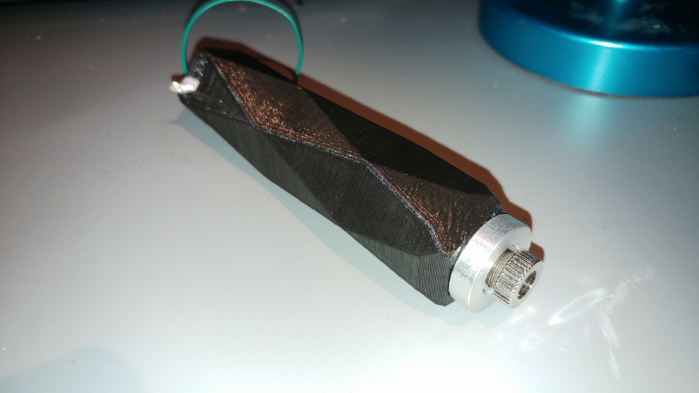
Finally I build a laser using it. I have no host laying around, so I printed one myself.
I did this once already for a 445nm 1W laser, but the host turned out quite ugly actually.
This time I wanted it to look a bit nicer. Using blender (free 3D modeling program) I designed a host. I really like those "low poly" pictures, so I tried to design a "low poly" host.
A few comments about the printing:
I used black PLA filament. Thats maybe a bit boring, but I have no other material here unfortunately. There exists glow-in-the-dark filament, which would surely look amazing on an 405nm laser.
The layer hight was 0.2mm. I could go down to 0.1mm but it took already 4h to print. I don't wanted to wait twice as long. I can share the .stl file for the host if somebody is interested. The model was sized up by 3% for printing because of shrinking of the material. PLA doesn't shrink that much, but 3% was almost to less. I had to do some finishing to get everything together.
So here are some pictures:
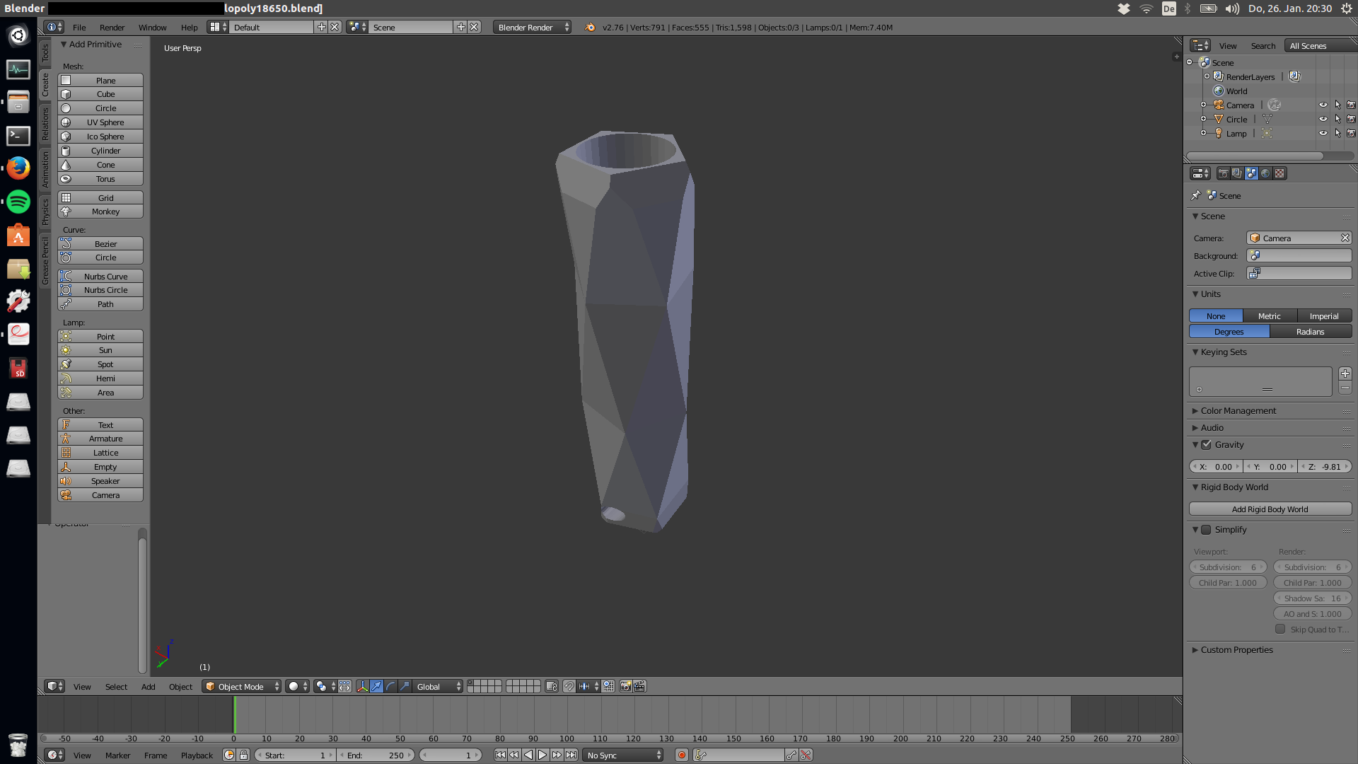
This is a screen shot of the host before being printed:
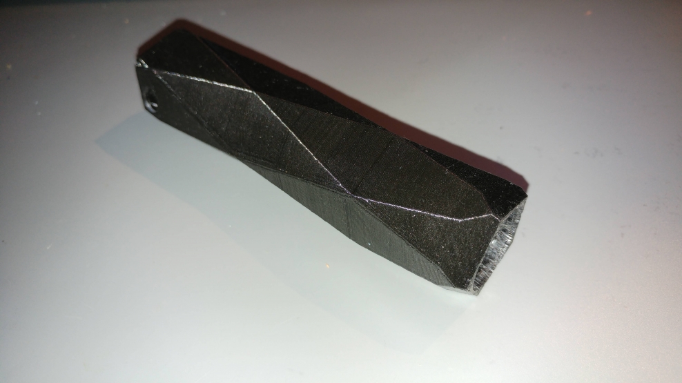
This is just the host, freshly printed:
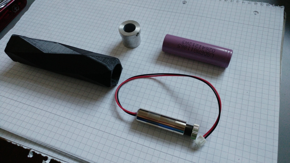
Here are all parts used in this build. I removed the long part of the laser module housing
in order to make it fit better. But those b*stards have glued the driver to the housing, so the first thing I did was braking of the diode from the driver. Luckily nothing got damaged, the solder joints broke off, not the pins.
There is place to add a switch. But I have no one laying around, so I used some wire to close the contact. The switch is like a splint pin. If I put it in, I can rotate it to close the contact. This is not ideal, I know, but a quick solution which works pretty well.
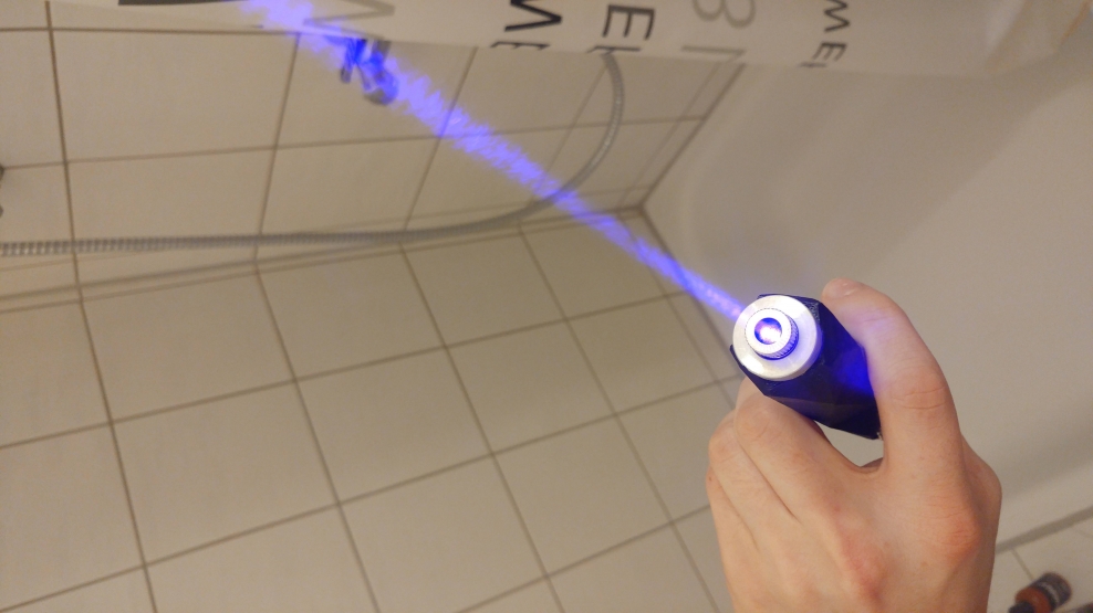
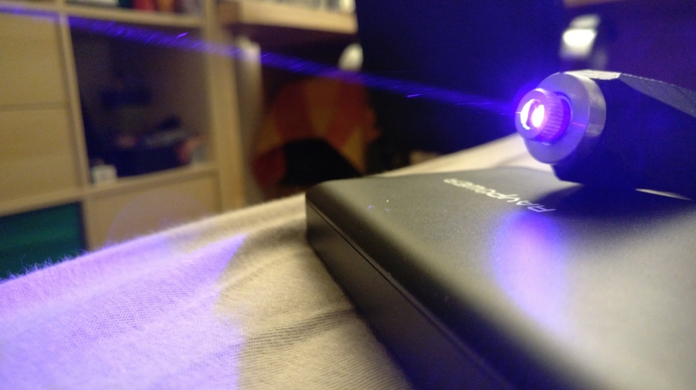
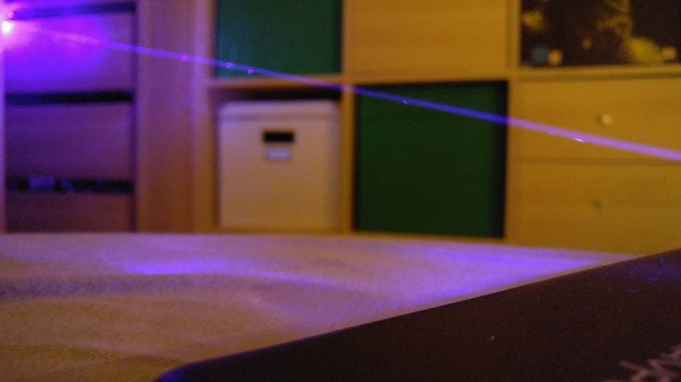
And the most important thing, some lasin'. Those pictures were taken with f1.8 ,iso 50 and 2s shutter speed using a smartphone:
I hope you like it
Greetings from Germany, MrMcChicken :beer:
So I had a second module which left over. I bought it in case I would screw one laser up.
They were advertised as 500mW lasers, but they are really not. I measured 110mW however thats no problem, they weren't expensive too. Back then I just needed some kind of 405nm laser and don't wanted to wait too long.
Finally I build a laser using it. I have no host laying around, so I printed one myself.
I did this once already for a 445nm 1W laser, but the host turned out quite ugly actually.
This time I wanted it to look a bit nicer. Using blender (free 3D modeling program) I designed a host. I really like those "low poly" pictures, so I tried to design a "low poly" host.
A few comments about the printing:
I used black PLA filament. Thats maybe a bit boring, but I have no other material here unfortunately. There exists glow-in-the-dark filament, which would surely look amazing on an 405nm laser.
The layer hight was 0.2mm. I could go down to 0.1mm but it took already 4h to print. I don't wanted to wait twice as long. I can share the .stl file for the host if somebody is interested. The model was sized up by 3% for printing because of shrinking of the material. PLA doesn't shrink that much, but 3% was almost to less. I had to do some finishing to get everything together.
So here are some pictures:
This is a screen shot of the host before being printed:

This is just the host, freshly printed:

Here are all parts used in this build. I removed the long part of the laser module housing
in order to make it fit better. But those b*stards have glued the driver to the housing, so the first thing I did was braking of the diode from the driver. Luckily nothing got damaged, the solder joints broke off, not the pins.

There is place to add a switch. But I have no one laying around, so I used some wire to close the contact. The switch is like a splint pin. If I put it in, I can rotate it to close the contact. This is not ideal, I know, but a quick solution which works pretty well.

And the most important thing, some lasin'. Those pictures were taken with f1.8 ,iso 50 and 2s shutter speed using a smartphone:


I hope you like it
Greetings from Germany, MrMcChicken :beer:


