Welcome to Laser Pointer Forums - discuss green laser pointers, blue laser pointers, and all types of lasers

LPF Donation via Stripe | LPF Donation - Other Methods

Links below open in new window

ArcticMyst Security by Avery

3.1W 9mm 445 fan cooled handheld

djQUAN

0
Joined
May 27, 2013
Messages
1,154
Points
63
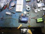
The design is not yet final but here are some stuff that I have finished. :)

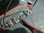
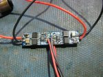
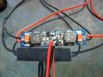
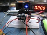
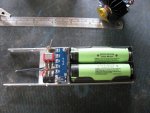
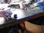
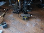
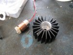
I started with a heatsink from FT (link) and machined it to accept a 12mm stubby module from DTR.
43724d1387084753-teaser-pics-work-progress-9mm-fan-cooled-handheld-img_0920.jpg


I like this new module (haven't seen it before) It makes good contact to the back part of the 9mm diode for better heatsinking.
43714d1386958816-dtr-s-laser-shop-1-5w-2w-m140-diodes-45-shipped-us-img_0899.jpg


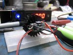
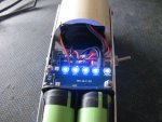
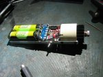
The heatsink does seem "a little" small for the job but this will be fan cooled so the large surface area with the fins will help. I won't know until I get this all arranged and powered up.

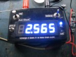
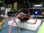
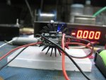
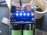
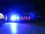
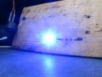
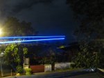
Once the module was in, I had to test it. First light!!! (fan behind the heatsink for cooling)
attachment.php


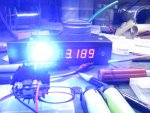
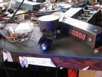
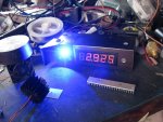
2.9W at 2.3A with a G2 lens.
attachment.php


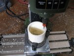
Machining makes a bit of aluminum dust
attachment.php


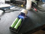
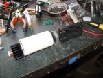
Planned arrangement of the parts
attachment.php


Heatsink and driver will be placed inside the PVC tube to make a wind tunnel for more efficient cooling.

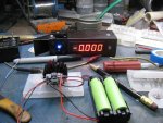
Since I got an average efficiency diode, I'll probably be underdriving this at around 2.2A for less heat. 2.5W should still be plenty for burning stuff. Hopefully, I get to complete this before the new year so that I can use it to light fireworks. :p
 

Attachments

  • IMG_0922.jpg
    IMG_0922.jpg
    118.1 KB · Views: 1,773
  • IMG_0923.jpg
    IMG_0923.jpg
    112.6 KB · Views: 1,724
  • IMG_0924.jpg
    IMG_0924.jpg
    118.3 KB · Views: 1,721
  • IMG_0926.jpg
    IMG_0926.jpg
    117.8 KB · Views: 1,841
  • IMG_0920.jpg
    IMG_0920.jpg
    96 KB · Views: 1,884
Last edited:


Joined
Feb 21, 2013
Messages
5,013
Points
0
Re: [Teaser pics, WIP] 9mm fan cooled handheld

Love to see how this turns out but slightly worried about the size of the heat sink. IMO its not large enough to handle a 9mm for more than 30sec on 60 off. Yes the area of the heatsink might be large but there isn't much material there.
 

djQUAN

0
Joined
May 27, 2013
Messages
1,154
Points
63
Re: [Teaser pics, WIP] 9mm fan cooled handheld

Yeah, I'm thinking about it too. But once I get to test it I'll change it if necessary to handle the heat of the 9mm.

Worst case, it'll end up as a labby with a larger fan haha
 

Zeebit

0
Joined
Aug 27, 2012
Messages
1,110
Points
0
Re: [Teaser pics, WIP] 9mm fan cooled handheld

Since it's actively cooled the heat shouldn't build up too much that when passively cooled. Well, at least in theory.

Why don't you entirely drill out the heatsink so that more of the module contacts the heatsink.
 

djQUAN

0
Joined
May 27, 2013
Messages
1,154
Points
63
Re: [Teaser pics, WIP] 9mm fan cooled handheld

That's all the depth my micro mill could drill into. :p I don't have a lathe in my workshop. I think it shouldn't be a problem since most of the thermal connection of the diode is at the back (aluminum back cover) so I made sure it sits flat with the heatsink with heat transfer compound all over.
 
Joined
Jun 25, 2011
Messages
1,481
Points
63
Re: [Teaser pics, WIP] 9mm fan cooled handheld

if you could get that copper module all the way in i think that heat sink will be plenty.
 

djQUAN

0
Joined
May 27, 2013
Messages
1,154
Points
63
Re: [Teaser pics, WIP] 9mm fan cooled handheld

It's the deepest I could drill using my micro mill. I would risk breaking the bit by going deeper and if I use a drill, the bottom surface won't be flat which won't get good thermal contact to the back of the module. We'll find out soon once I can do some more tests :)
 

djQUAN

0
Joined
May 27, 2013
Messages
1,154
Points
63
Re: [Teaser pics, WIP] 9mm fan cooled handheld

A little update on the electronics side. (For those that don't care about how the circuit will work, just scroll down for the pics :p )

We start with an off the shelf driver. We take two of [this] and modify it.

The circuit is basically what's in the LTC1700 datasheet. Even the part numberings on the PCB are the same!

So this "driver" is basically a 4.2V to 5.18V step up DC to DC converter with a 1 ohm current limiting resistor. Much like you'd add a resistor in series with an LED to be able to operate it in higher voltages. It works but isn't very efficient and a small change in the diode Vf changes the output current and we don't want that.

The solution? I used a ZXCT1009 inserted in the circuit feedback path and a few parts changes to make it a constant current supply. So we set one at around 1.1A, the other at 1.4A and then parallel them. Add switches and connect them to the RUN/SS pin of the LTC1700 and you can control the output much like a TTL control ;)

I used two in parallel since I'd need over 2 amps for the 9mm diode and I've tested that one could push up to only 1.8A.

The advantage would be by using two buttons, pressing only one gives either 1.1A or 1.4A current, then by pressing both at the same time, you get full power!:eg:

This is getting too long. On with the test setup pics.

Modified drivers wired in parallel
attachment.php

attachment.php


I changed the inductors since the original one cracked from too much fiddling. I didn't have the right value on hand so I used the nearest one.
attachment.php


Test setup. Large string of 3A diodes and amp meter test load. Power source is 2x Panny 3400 cells in parallel.
attachment.php


Both drivers ON. Sorry it's fuzzy, camera couldn't focus on the display
attachment.php


I might drop the maximum current by a few notches but I didn't have the right resistor value so I'll be rummaging through the scrap boards but it's getting late so it'll have to wait.
 

Attachments

  • IMG_0980.jpg
    IMG_0980.jpg
    124.3 KB · Views: 1,590
  • IMG_0981.jpg
    IMG_0981.jpg
    128.7 KB · Views: 1,556
  • IMG_0984.jpg
    IMG_0984.jpg
    82.6 KB · Views: 1,610
  • IMG_0986.jpg
    IMG_0986.jpg
    130.7 KB · Views: 1,583
  • IMG_0987.jpg
    IMG_0987.jpg
    108.7 KB · Views: 1,650

djQUAN

0
Joined
May 27, 2013
Messages
1,154
Points
63
Re: [Teaser pics, WIP] 9mm fan cooled handheld

A little more work done tonight.

I decided 2.5amps might be a little too hot so I put both drivers back to 1.1A. Then I was able to make a small bracket/heatsink that mounts behind the diode heatsink.

The white rubbery thing in between the drivers and the heatsink in the middle is thermally conductive silicone pad.
attachment.php

attachment.php

attachment.php

attachment.php


Here it is powered up and the drivers in standby mode
attachment.php


I used only one button for now and when you push it...
attachment.php
 

Attachments

  • IMG_1017.jpg
    IMG_1017.jpg
    94.2 KB · Views: 1,490
  • IMG_1019.jpg
    IMG_1019.jpg
    94.6 KB · Views: 1,488
  • IMG_1018.jpg
    IMG_1018.jpg
    114.2 KB · Views: 1,517
  • IMG_1016.jpg
    IMG_1016.jpg
    92.3 KB · Views: 1,518
  • IMG_1015.jpg
    IMG_1015.jpg
    96.4 KB · Views: 1,531
  • IMG_1014.jpg
    IMG_1014.jpg
    96 KB · Views: 1,498

djQUAN

0
Joined
May 27, 2013
Messages
1,154
Points
63
Re: [Teaser pics, WIP] 9mm fan cooled handheld

Today's progress:

I made a bracket/sled type thingy to hold the batteries, switch and everything else together.
attachment.php


I also added a battery gas gauge so I know when the batteries need charging. This thing draws about 3-4amps from the batteries since I used two boost drivers.
attachment.php


I was supposed to go to the farm on Wednesday to use the lathe there but I couldn't wait so off to my micro mill again. :)

I let it go as deep as I could and used the shortest lenght of PVC that can hold the heatsink in place so it would fit in my mill.
attachment.php


Seems to ave worked. :) Here it is assembled and in standby mode.
attachment.php


Toggle switch is the main power switch. Pressing the button opposite the toggle switch turns the laser to full power
attachment.php


3.1Watts of blue! Sorry about the blurry pics. My hands were a little more shaky than usual at the moment. :na:
attachment.php
 

Attachments

  • IMG_1020.jpg
    IMG_1020.jpg
    100 KB · Views: 1,464
  • IMG_1021.jpg
    IMG_1021.jpg
    112.6 KB · Views: 1,478
  • IMG_1022.jpg
    IMG_1022.jpg
    93.7 KB · Views: 1,506
  • IMG_1023.jpg
    IMG_1023.jpg
    115.6 KB · Views: 1,503
  • IMG_1024.jpg
    IMG_1024.jpg
    95.8 KB · Views: 1,522
  • IMG_1025.jpg
    IMG_1025.jpg
    91.9 KB · Views: 1,464
Joined
Dec 14, 2013
Messages
19
Points
3
Even after a year since giving up facebook (new years resolution 2013) I find myself looking for the "like" button on this post. I've kept an eye on this build. Nice job. What color of spray paint are you going to finish it off with? Merry Christmas!:beer:
 

djQUAN

0
Joined
May 27, 2013
Messages
1,154
Points
63
Thanks, I'm not really sure yet. The PVC tube is sort of temporary and I also need to make a cover for the electronics part. I think I also need to make a guard for the fan. My finger touched the blades a few times while playing with it haha
 
Joined
Dec 14, 2013
Messages
19
Points
3
I wonder if a black plastic stand-up extension tube for a shop vac would be the right size for the external sleeve?

Questions, can you hear the fan? I know it might sound a little silly, but I've been thinking about some sort of sound effect when the rig fires up.

Blue and orange might look cool.....
 

djQUAN

0
Joined
May 27, 2013
Messages
1,154
Points
63
My other issue would be that I think paint has a hard time sticking to PVC. I'll try and keep a lookout for a nicer tube.

The fan is a little noisy since it is not the best quality but it does the job :)

One thing I noticed, I powered this on side by side with my 1.7W and this one is a lighter blue. I'm guessing it's a shorter wavelength. 445nm? 440nm? Let's see if the camera can pick it up...
 
Last edited:

Zeebit

0
Joined
Aug 27, 2012
Messages
1,110
Points
0
Lighter blue? It should be higher than 445nm then.

You have a lot of interesting builds lately. Keep us posted.

Rep when I can. :)
 

djQUAN

0
Joined
May 27, 2013
Messages
1,154
Points
63
Haha sorry my mistake. I was typing in a hurry and mixed them up.

It's christmas vacation so I have a bit of spare time to work on laser stuff :beer:

Here are some pics I took just now.

I think I'll keep the PVC. Having the heatsink protrude just a bit allows me to touch it and see if it's getting hot
attachment.php


LPM reading
attachment.php


Scorch marks
attachment.php


Everyone's favorite... Top: 1.7W laser Bottom: 3W laser
attachment.php
 

Attachments

  • IMG_1026.jpg
    IMG_1026.jpg
    119.4 KB · Views: 1,415
  • IMG_1028.jpg
    IMG_1028.jpg
    59.4 KB · Views: 1,415
  • IMG_1037.jpg
    IMG_1037.jpg
    66.8 KB · Views: 1,421
  • IMG_1041.jpg
    IMG_1041.jpg
    80.8 KB · Views: 1,501


Top