Welcome to Laser Pointer Forums - discuss green laser pointers, blue laser pointers, and all types of lasers

LPF Donation via Stripe | LPF Donation - Other Methods

Links below open in new window

ArcticMyst Security by Avery

3.1W 9mm 445 fan cooled handheld


djQUAN

0
Joined
May 27, 2013
Messages
1,154
Points
63
Not much laser posts from me so here's an update.

I wanted to make this laser look a little better so I decided to replace the fan/heatsink assembly with something different.

It all starts with a solid block of aluminum.
attachment.php


After milling all the sides to make it perfectly flat, the guts from the previous design are laid over to plan for the placement.
attachment.php


I started with the pockets for the dual drivers.
attachment.php


I didn't take a step by step pic of the heatsink as it took shape as I was on a roll but here is the mess I made with it afterwards.
attachment.php


I didn't have a 12mm drill bit on hand so I went around the local hardware stores but all of them only sold drill bits in inches. the closest I had on hand was 11.85mm so I improvised to make the hole slightly bigger. A strip of sandpaper attached to the dremel made quick work and satisfactory fit of the module in the heatsink.
attachment.php


And here's the nearly completed heatsink. I took me the entire day to get this far. I was working the mill to its limits since it is meant for small pieces only.
attachment.php

attachment.php


Temporarily connected everything and tested it. It still works!
attachment.php


Here it is wired and cleaned up.
attachment.php


Yeah I need to do something with the exposed driver.
attachment.php


Yep. exposed driver!
attachment.php


But I think it looks se×ier now compared to the previous iteration :)
attachment.php

attachment.php


Yup. Still got it!
attachment.php


And it was a little foggy out so here's what you guys like to see. Beam shots!
attachment.php


And because I wanted to have a reason to put this here haha. Here's a thermal shot of the laser after running a few minutes. I need to do something about those battery springs.
attachment.php
 

Attachments

  • IMG_3647.jpg
    IMG_3647.jpg
    230 KB · Views: 392
  • IMG_3648.jpg
    IMG_3648.jpg
    218.6 KB · Views: 374
  • IMG_3649.jpg
    IMG_3649.jpg
    303.4 KB · Views: 372
  • IMG_3653.jpg
    IMG_3653.jpg
    246.2 KB · Views: 345
  • IMG_3656.jpg
    IMG_3656.jpg
    230.5 KB · Views: 363
  • IMG_3659.jpg
    IMG_3659.jpg
    232.9 KB · Views: 374
  • IMG_3658.jpg
    IMG_3658.jpg
    270.6 KB · Views: 365
  • IMG_3645.jpg
    IMG_3645.jpg
    251.5 KB · Views: 352
Last edited:

djQUAN

0
Joined
May 27, 2013
Messages
1,154
Points
63
*for pics*
 

Attachments

  • FLIR0069.jpg
    FLIR0069.jpg
    130.9 KB · Views: 306
  • IMG_3675.jpg
    IMG_3675.jpg
    197 KB · Views: 465
  • IMG_3669.jpg
    IMG_3669.jpg
    233.9 KB · Views: 349
  • IMG_3667.jpg
    IMG_3667.jpg
    264.9 KB · Views: 354
  • IMG_3665.jpg
    IMG_3665.jpg
    149.3 KB · Views: 441
  • IMG_3662.jpg
    IMG_3662.jpg
    254.7 KB · Views: 350
  • IMG_3660.jpg
    IMG_3660.jpg
    242.2 KB · Views: 360
  • IMG_3666.jpg
    IMG_3666.jpg
    228.7 KB · Views: 361
Last edited:
Joined
Jan 29, 2012
Messages
3,164
Points
113
Looks amazing. Great job and +3. ;) :beer:
 
Last edited:

djQUAN

0
Joined
May 27, 2013
Messages
1,154
Points
63
So I worked on this some more and thought about making it a little bit shorter.

I also wanted to have a forward clicky type switch so the tact switch had to go. I used a reverse clicky switch since shorting the driver enable pin to ground turns the laser off. Using a reverse clicky switch this way results to a forward clicky operation of the laser. Not making sense? it's hard to explain but it works ;) 
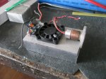
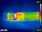
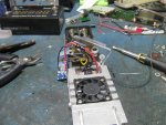
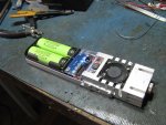
I also wired the fan to the driver output before the sense resistor so it would not affect driver output current and I could eliminate a third dc-dc converter from the entire laser.
attachment.php


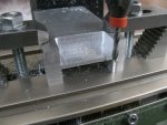
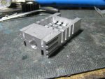
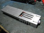
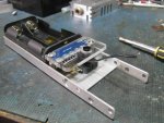
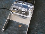
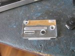
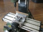
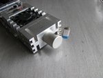
A new cover is needed so off to the mill with a piece of acrylic.
attachment.php


After an hour of milling, this is the finished part
attachment.php


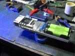
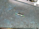
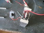
Glued in the pinheader that will serve as both a keyswitch and charging port.
attachment.php


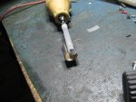
Glued the clicky switch in place
attachment.php


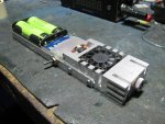
Test fitting the buttons and cover
attachment.php


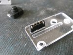
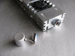
This will be the key. The pins on the laser are arranged so that shorting certain pins connects the driver to the battery. The middle pin is also ground so we have direct access to the batteries through this port for charging. I will tie this key with a short string to a lens cap. This way, there will be no chance of burning the lens cap since you have to take it off to attach the key to the pinheader slot.
attachment.php


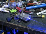
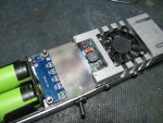
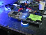
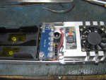
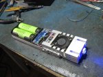
Wired it and ready to be buttoned up.
attachment.php


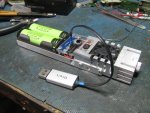
Here it is put together. The place on the battery meter can be a convenient location for a laser warning sticker :rolleyes:
attachment.php


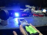
And it works! Key switch plugged in
attachment.php


Push the black button to get black burn spots
attachment.php


And it's totally USB2.0 compliant!
attachment.php


I replaced the focus ring with a longer one I scavenged from a pen build
attachment.php


And it turned out the cap for a spray perfume made a perfect fit as a lens cap. I also tied the key to it so there's no risk of firing the laser with the cap on.
attachment.php


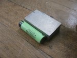
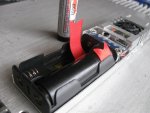
I also added a ribbon to the battery holder to more easily remove the batteries if they need to be replaced or recharged through an external battery charger.
attachment.php
 

Attachments

  • IMG_3683.jpg
    IMG_3683.jpg
    208.8 KB · Views: 316
  • IMG_3685.jpg
    IMG_3685.jpg
    247.6 KB · Views: 288
  • IMG_3684.jpg
    IMG_3684.jpg
    226 KB · Views: 339
  • IMG_3681.jpg
    IMG_3681.jpg
    230 KB · Views: 311
  • IMG_3680.jpg
    IMG_3680.jpg
    208.6 KB · Views: 311
  • IMG_3679.jpg
    IMG_3679.jpg
    223.8 KB · Views: 323
  • IMG_3678.jpg
    IMG_3678.jpg
    234.8 KB · Views: 285
  • IMG_3677.jpg
    IMG_3677.jpg
    206.6 KB · Views: 345
Last edited:

djQUAN

0
Joined
May 27, 2013
Messages
1,154
Points
63
*for pics*
 

Attachments

  • IMG_3686.jpg
    IMG_3686.jpg
    233.8 KB · Views: 315
  • IMG_3689.jpg
    IMG_3689.jpg
    236.8 KB · Views: 309
  • IMG_3690.jpg
    IMG_3690.jpg
    236.6 KB · Views: 285
  • IMG_3691.jpg
    IMG_3691.jpg
    235.4 KB · Views: 334
  • IMG_3692.jpg
    IMG_3692.jpg
    202.3 KB · Views: 333
  • IMG_3696.jpg
    IMG_3696.jpg
    184.9 KB · Views: 351
  • IMG_3695.jpg
    IMG_3695.jpg
    184.7 KB · Views: 386
Last edited:
Joined
Feb 25, 2010
Messages
1,643
Points
113
Just saw this build thread. Great work !! Many new ideas and work arounds...mmm

I will likely...er...ah...borrow several of your ideas !!! THANX !!!!!

I suppose it is all depending on what duty cycle one is aiming for as to the utility of air cooling !! Surly it really extends the duty cycle and pulls heat away from the LD heat sink...which in turn allows for a greater current max.

ALWAYS trade-offs !! For me...A new goal is as small as possible...with as much W !!
Maybe a very small build with a laptop type cooler/heatsink. The laptop computer folks have opened the path for small, efficient thermal management to pull heat away from the CPU. Might be good to use their technology and off the shelf mini parts ??

You've got me thinking !!! Thanx again for sharing and ALL the pics !!! It is great to see the build or builds unfold !! VERY educational !!!

Nice use of the rectangular form factor and Acrylic to show some guts !!
 
Last edited:

djQUAN

0
Joined
May 27, 2013
Messages
1,154
Points
63
Thanks. "borrow" all you want. ;)

The fan does help a lot on the duty cycle. I tried running it with the fan disconnected and the heatsink does get warmer much quicker. With the fan on, the heatsink gets warm but never hot even when run 100% duty cycle until the batteries run out.
 

zenon

0
Joined
Aug 20, 2012
Messages
6
Points
1
Hello

Does anyone know what thread , tap size for the copper laser diode host ,
I would like to screw the Copper host in to a larger block , Thanks
 
Joined
Jul 10, 2015
Messages
9,799
Points
113
Looks like M11 x 0.5
I have a M12 x 0.5 and it's too big, sorry I don't have a M11 x 0.5 to check it, but that's what it looks like.


Top