3zuli
0
- Joined
- May 30, 2009
- Messages
- 810
- Points
- 28
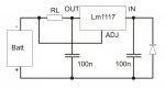
I saw the datasheet of lm1117 and it says it can supply 800mA, but it needs cooling (heatsink)


Follow along with the video below to see how to install our site as a web app on your home screen.
Note: This feature may not be available in some browsers.


I saw the datasheet of lm1117 and it says it can supply 800mA, but it needs cooling (heatsink)
")
 ..... not sure, have to see tomorrow, but in this way, maybe i can fit all in the space that then you can dip in the thermal silicone
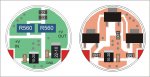
Yes, this is the reason for use 3 of them (so each one hold 433mA), and for dip them in thermally conductive silicone (so the glue can transfer the heat from the components to the case)
Edit: hell, it's a damn pain you-know-where, to fit all the components in less than 16mm of diameter ..... you said that you have 15mm of deep in the lower portion of the cylinder, mind if it take 12 or 13mm of thickness and is on 2 discs ?
BTW, i forgot to ask you if you need that it have a side as contact for the battery, or if is wired.

 ..... played a bit with coreldraw, and found that, if you can end with 25mm of diameter (or also 24) in the low part, i can fit all on a single board, and there's also too much free space (relatively talking ), and overall keep all the 3 regulators on a single side (the bottom side), so you can thermally couple it in two ways, depend if the space is opened or closed.
 ), but i have to say that, first, the 137 have a dropout of at least 2V, so you need a bit more voltage for the input, and they dissipate a bit more power in heat, and second, opposite than for the 1117, that i already used them in parallel with success, i never tried to use the 137 in parallel, til now, so i don't know how they work in these conditions, especially for the long times.