Welcome to Laser Pointer Forums - discuss green laser pointers, blue laser pointers, and all types of lasers

Buy Site Supporter Role (remove some ads) | LPF Donations

Links below open in new window

FrozenGate by Avery

10 Watt 808nm Diode, Max it can be overdriven too?

53293d1475178965-10-watt-808nm-diode-max-can-overdriven-too-jjhsj2.jpg


.......................................................So the input (left) end of the KTP has a High Reflector. Correct?


.
 

Attachments

  • jjHSJ2.jpg
    jjHSJ2.jpg
    158.8 KB · Views: 128
Last edited:


.......................................................So the input (left) end of the KTP has a High Reflector. Correct?


.

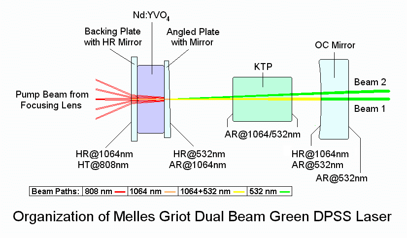
It may have an HR@532nm coating on the input side, it'll have AR@1064nm on both ends and AR@532nm on at least one end. It could also have AR@532nm on both ends. The Nd:YVO4 will have an HR@1064nm and AR@808nm coating on the input side to the left - It could also have HR@532nm on the output side of the YVO4, or less likely but still possible, on the input side - of course that means the KTP is AR/AR@532 AND 1064nm.

Edit: For example, here's how it's done in the Melles heads I have (pictured in my sig):

mgdbl1.gif


Yes, you read that right, the OC for green is AR@532nm - there's no need to circulate the 532nm beam in the cavity.

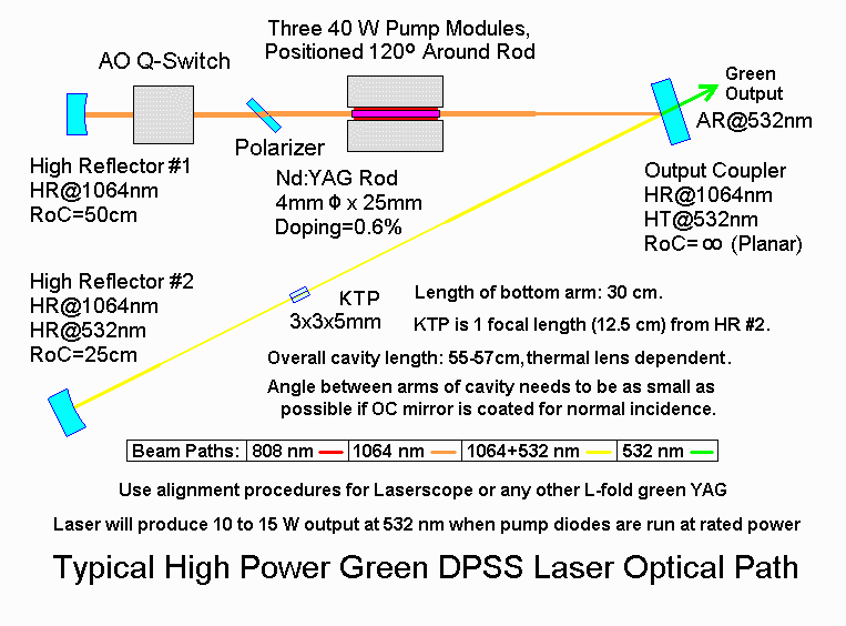
Another example here:

dpss2asm.gif
 
Last edited:
So the OC and AR 532nm coating manage the KTP?

53296d1475179805-10-watt-808nm-diode-max-can-overdriven-too-jjhsj2d.jpg
 

Attachments

  • jjHSJ2d.jpg
    jjHSJ2d.jpg
    174.7 KB · Views: 145
Last edited:
So the OC and AR 532nm coating manage the KTP?

53296d1475179805-10-watt-808nm-diode-max-can-overdriven-too-jjhsj2d.jpg


Yep, that looks about right to me.

The AR@808 coating is also going to be HR@1064nm.

The output side of the YVO4 is likely to be AR@1064 and HR@532, the KTP will be AR@1064 and 532 on both ends. The OC will be HR@1064 and AR@532nm. That's how I've most often seen it done in these linear cavities anyway - although it doesn't need to be exactly that way.

Probably one of the best resources for understanding basic DPSS processes: http://www.repairfaq.org/sam/lasercds.htm

There's a good chart on that page with example optics for different powers:

Power Output: 5 mW 20 mW 100 mW 1 W 5 W
-------------------------------------------------------------------------------
Pump Diode (1)
Maximum Power 100 mW 500 mW 1 W 10 W 50 W
TEC Thermal Power -- 1 W 3 W 30 W 150 W
Beam Correction <-- uLens or None --> Prisms <-- Fiber-coupled -->

Resonator (2)
Type <-------- Hemispherical -------> <--- Long Radius --->
Length 7 mm 15 mm 40 mm 80 mm 150 mm

HR Mirror (3)
Diameter --- --- --- 10 mm 15 mm
RoC --- --- --- 250 mm 500 mm

Vanadate:
Overall Size 2x2x0.5mm 3x3x1.2 mm 3x3x1.2 mm 3x3x3 mm 4x4x4 mm
Doping Level 3% 1% 1% 0.7% 0.7%
Side 1 Coatings HT@808nm HT@808nm HT@808nm HT@808mn HT@808nm
HR@1064nm HR@1064nm HR@1064nm AR@1064nm AR@1064nm
Side 2 Coatings AR@1064nm AR@1064nm AR@1064nm AR@1064nm AR@1064nm
TEC Thermal Power --- 0.5 W 1 W 4 W 20 W

KTP (4)
Overall Size 2x2x3 mm 2x2x5 mm 2x2x5 mm 3x3x7 mm 3x3x7 mm
Type <------------ Flux Grown --------> <-- Hydrothermal -->
Side 1 Coating AR@1064nm AR@1064nm AR@1064nm AR@1064nm AR@1064nm
Side 2 Coating AR@1064nm AR@1064nm AR@1064nm AR@1064nm AR@1064nm
Heater Power --- 0.5 W 0.5 W 1 W 2 W

OC Mirror (5)
Diameter 5 mm 5 mm 5 mm 10 mm 15 mm
RoC 10 mm 20 mm 50 mm 100 mm 200 mm
Side 1 Coatings HR@1064nm HR@1064nm HR@1064nm HR@1064nm HR@1064nm
AR@532nm AR@532nm AR@532nm AR@532nm AR@532nm
Side 2 Coatings AR@532nm AR@532nm AR@532nm AR@532nm AR@532nm

Which didn't format properly so here's a direct link... http://www.repairfaq.org/sam/lasercds.htm#cdscsch
 
Last edited:
Great visual representation diachi, once again you amaze me of your knowledge. It makes 99% sense to me now in terms of the theory of operation. So it sounds like if I just replace the HRs with a 1123nm coating and the ARs with a 560nm coating and use LBO instead of KTP I should get my 560nm laser :D
 
Great visual representation diachi, once again you amaze me of your knowledge. It makes 99% sense to me now in terms of the theory of operation. So it sounds like if I just replace the HRs with a 1123nm coating and the ARs with a 560nm coating and use LBO instead of KTP I should get my 560nm laser :D


Nope - crystal coatings need to be correct too, so you'd need to change the crystals. Can't just swap the cavity mirrors. And in plenty of cases the HR mirror is coated onto the YVO4, so you can't change that without changing the crystal anyway. <<-----Ignore everything before here :p

Most other YVO4 transitions (outside of 1064nm) are significantly lower gain than 1064nm so they are even harder to get lasing - making the coatings/alignment/optics quality/cavity design and temperature stabilization even more important.

Edit: Sorry - I misread that - thought you said just change the mirrors and keep the crystals. Then yes, in theory, that's "all" you need to do. Not quite that simple in practice...

The yellows may favour a different dopant percentage in YVO4 too - I don't know the answer to that. I'd need to do some digging.

I've spent weeks (months even) on end reading scientific papers, forum posts, websites and Sam's FAQ and I'm not even 100% certain on a lot of this stuff ;) Hell, I'd say I'm not even 99% certain on a lot of DPSS design and theory. I'm sure I could do several degrees in these fields and still not have a complete, detailed understanding of how all of it works.
 
Last edited:
Ok High Reflective and Anti Reflective, makes you appreciate those 532nm modules, that and the awesome beam quality. :beer:

Minus the mode hopping, often the mode hop is not that noticeable at distance, but it would effect burning ability.


These are from small 532's, the ND-YV04 and KTP are bonded, but separating the crystals seems to be the method for higher power units.
You can see a gradient index lens still glued to some.
I have a bunch of loose crystal pairs somewhere that show the bond line, but they are likely about useless.

53297d1475181710-10-watt-808nm-diode-max-can-overdriven-too-sany0696.jpg
 

Attachments

  • SANY0696.JPG
    SANY0696.JPG
    198.6 KB · Views: 136
Last edited:
Nope - crystal coatings need to be correct too, so you'd need to change the crystals. Can't just swap the cavity mirrors. And in plenty of cases the HR mirror is coated onto the YVO4, so you can't change that without changing the crystal anyway. Most other YVO4 transitions (outside of 1064nm) are significantly lower gain than 1064nm so they are even harder to get lasing - making the coatings/alignment/optics quality/cavity design and temperature stabilization even more important.

The yellows may favour a different dopant percentage in YVO4 too - I don't know the answer to that. I'd need to do some digging.

Probably why Shalomeo uses a Nd:YAG + MgO:PPLN system instead of the orthovanadate
 
Probably why Shalomeo uses a Nd:YAG + MgO:PPLN system instead of the orthovanadate

Dopant % may have an effect in YAG too for Yellow vs Green. Not sure.

They'll be using YAG because YVO4 doesn't have the appropriate transitions (notably 1123 and 1319). YVO4 is suitable for 915nm,1064nm and 1340nm (summing of 1064 and 1340 would produce 593nm). 1064nm and 1319nm from YAG would sum to 588.9nm or 589nm if you're rounding.

Note: There will likely be other transitions but those are the major ones.
 
Last edited:
Since I feel pretty humbled by the vast knowledge of some of the members here I am going to spend a few weeks reading up on these interactions of laser light with crystals. I found this website where I am going to start my at-home research, Covesion Ltd. - Covesion Guide to PPLN, it seems like a lot of good current information on DPSS materials. Anyway I thought I'd share it with you as it relates to using IR pumped light to achieve independently assorted wavelengths.
 
Since I feel pretty humbled by the vast knowledge of some of the members here I am going to spend a few weeks reading up on these interactions of laser light with crystals. I found this website where I am going to start my at-home research, Covesion Ltd. - Covesion Guide to PPLN, it seems like a lot of good current information on DPSS materials. Anyway I thought I'd share it with you as it relates to using IR pumped light to achieve independently assorted wavelengths.

Check the Sam's FAQ link I posted earlier too.

Here it is again: Sam's Laser FAQ - Home-Built Diode Pumped Solid State (DPSS) Laser


Although as I mentioned, a quick read of laser fundamentals may be good too.

Before long you'll be reading all sorts of scientific papers. :p
 
The OC is kind of like the Brewster's angle of a gas laser.

No. The "brewster's angle" is not a device, it's an angle. A brewster window is a pane of glass (typically) situated at brewster's angle to prevent losses from this resonator window. The OC is a completely separate device. Look up the wikipedia page on these things. Relying on one or two sentences from an internet stranger isn't ideal for a topic like this.
 
No. The "brewster's angle" is not a device, it's an angle. A brewster window is a pane of glass (typically) situated at brewster's angle to prevent losses from this resonator window. The OC is a completely separate device. Look up the wikipedia page on these things. Relying on one or two sentences from an internet stranger isn't ideal for a topic like this.

Wiki page for those that are lazy: https://en.wikipedia.org/wiki/Brewster's_angle

Worth noting that the window only prevents losses for one type of polarization - which is handy because that polarization then has the lowest round trip losses in the cavity, meaning you end up with a polarized output beam. The Wiki article only talks about gas lasers but Brewster windows are used in a variety of lasers that are not inherently polarized.
 
Dopant % may have an effect in YAG too for Yellow vs Green. Not sure.

They'll be using YAG because YVO4 doesn't have the appropriate transitions (notably 1123 and 1319). YVO4 is suitable for 915nm,1064nm and 1340nm (summing of 1064 and 1340 would produce 593nm). 1064nm and 1319nm from YAG would sum to 588.9nm or 589nm if you're rounding.

Note: There will likely be other transitions but those are the major ones.

So you did that calculation via SFG right, so how do you know what crystal produces an SFG, SHG, or a DFG?
 
So you did that calculation via SFG right, so how do you know what crystal produces an SFG, SHG, or a DFG?


If you know about a variety of different non-linear optical crystals then you can look at the specifications/applications of those crystals to determine which is most suitable for your application. Generally there will be a few different crystals that will work but some will be better suited than others, either due to cost, mechanical properties or optical properties.
 
Last edited:


Back
Top