Welcome to Laser Pointer Forums - discuss green laser pointers, blue laser pointers, and all types of lasers

LPF Donation via Stripe | LPF Donation - Other Methods

Links below open in new window

ArcticMyst Security by Avery

10 Watt 808nm Diode, Max it can be overdriven too?

CurtisOliver

0
LPF Site Supporter
Joined
Jun 12, 2015
Messages
7,610
Points
113
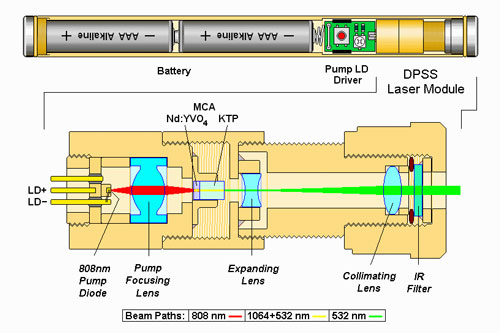
No you need to first pump a Nd:YVO4 crystal with special AR coatings for both 1064nm and 1319nm. When you pump a crystal you can get more than one of its transition lines. Then secondly you must phase match the new IR beams into the KTP. I hope this clarifies things.
For 589nm it is a ND:YAG crystal lasing at both 1064nm and 1319nm. The process being used in the yellows is called sum frequency generation (SFG) not SHG.


Joined
Mar 25, 2016
Messages
475
Points
0
Is the only thing which makes this 594nm the AR coating, assuming it has one, if that is the case?

You need two crystals, the Nd:YVO4 and the KDP. But the companies that make them put them in a module together.
 
Last edited:
Joined
Jan 14, 2009
Messages
1,452
Points
83
Fiber coupled diodes are the best for focusing for engraving and that , single emitter IR diodes are not to bad either but the CCP diodes are more of a pain due to the 19 emitters unless they are coupled to fibers .

Pusing the diodes isn't the best idea , go to far and it could cause optical failure

7W 940nm fiber coupled diode with 1 meter fiber , I used single lens to focus it , drive current was 8.5A , Its funny though a camera without and IR filter to see the fiber glow : D

 
Last edited:
Joined
Jul 10, 2015
Messages
9,908
Points
113
The crystals in 532nm lasers look like 2 parts optically bonded, the 1st converts 808 to 1064 and the 2nd half 1064 doubles to 532.

I did not think it was a coating although they do have a coating.

I have a bunch of crystals and they are made of 2 parts.

I can take some close up pics with my microscope, but I cam see with a magnifying glass they are 2 parts bonded.

Here's an explanation.


Green-laser-pointer-dpss-diagrams.jpg


So the 1st part is neodymium doped - yttrium aluminum garnet and the 2nd part called KTP is Potassium titanyl phosphate....Correct?


NdYVO4CrystalLasing.jpg
 
Last edited:

diachi

0
Joined
Feb 22, 2008
Messages
9,700
Points
113
The crystals in 532nm lasers look like 2 parts optically bonded, the 1st converts 808 to 1064 and the 2nd half 1064 doubles to 532.

I did not think it was a coating although they do have a coating.

I have a bunch of crystals and they are made of 2 parts.

I can take some close up pics with my microscope, but I cam see with a magnifying glass they are 2 parts bonded.

Here's an explanation.

th


Green-laser-pointer-dpss-diagrams.jpg


So the 1st part is neodymium doped yttrium aluminum garnet and the 2nd part called KTP is Potassium titanyl phosphate.


That's the case for lower power/cheaper pointers DPSS pointers, but higher power or exotic wavelength pointers will still use discrete crystals and a discrete OC mirror. The HR is usually coated onto the Vanadate in that case (Note, the OC is also HR at 1064nm, but I'm referring to the pump input HR on the Vanadate/Diode end).

See top left and bottom diagrams:

dpss1.gif


Yours are still good examples for lower power/cheaper 532nm pointers though!
 
Last edited:
Joined
Jan 14, 2009
Messages
1,452
Points
83
This is a 1W CNI 532nm head , its doing just over 1.65W

The ND:YVO4 is a cube in the beging of the brass mount and the KTP is in the middle in the lower down rectangle piece and output coupler is mounted on the aluminium piece to the far right

: D

IMG_0504[1] by TwirlyWhirly555, on Flickr
 
Last edited:
Joined
Mar 25, 2016
Messages
475
Points
0
What I'm wondering is how some Nd:YVO4 crystals pump 808nm light into 1064nm and the others pump 808nm light into 1123nm. I would like to do this because it should produce 560nm light when frequency doubled. I can't find the answer but I am still searching :p
 
Joined
Jan 14, 2009
Messages
1,452
Points
83
What I'm wondering is how some Nd:YVO4 crystals pump 808nm light into 1064nm and the others pump 808nm light into 1123nm. I would like to do this because it should produce 560nm light when frequency doubled. I can't find the answer but I am still searching :p

The ND:YVO4 has transitions it will lase at , for it to even lase it has to be placed inside a cavity that will allow gain at the target wavelength required hense why there is an OC and HR at each end of the cavity and they are coated at the target wavelength you want the ND:YVO4 to lase at ( coatings on these will determine what lases )

The 808nm is absorbed by the ND:YVO4 and it fluoresces ( emits light with a lower energy than what it was pumped with ) When this happens inside a cavity and there is sufficient gain it will begin " lasing "

The ND:YVO4 will only lase on transitions that it has and for this to happen it has to be inside a cavity .
 
Last edited:
Joined
Mar 25, 2016
Messages
475
Points
0
The ND:YVO4 has transitions it will lase at , for it to even lase it has to be placed inside a cavity that will allow gain at the target wavelength required hense why there is an OC and HR at each end of the cavity and they are coated at the target wavelength you want the ND:YVO4 to lase at ( coatings on these will determine what lases )

The 808nm is absorbed by the ND:YVO4 and it fluoresces ( emits light with a lower energy than what it was pumped with ) When this happens inside a cavity and there is sufficient gain it will begin " lasing "

The ND:YVO4 will only lase on transitions that it has and for this to happen it has to be inside a cavity .

Nice great info, but what are the OC and HR? Do you know which coatings determine what wavelength lases? I am familiar with formulas and optics, but the materials science eludes me, much thanks :beer:
 
Joined
Jul 10, 2015
Messages
9,908
Points
113
If it uses an output coupler then there must be a partially reflective coating on the input end of that last crystal - the KTP, that's the gain medium, that's a separate crystal design.

Is that correct ?

https://en.wikipedia.org/wiki/Output_coupler

275px-Laser.svg.png


The 1064nm enters the KTP that is reflective on the inside of the input side and the OC - output coupler is a semi reflective mirror that uses the KTP as a gain medium cavity, this must add to the high beam quality.
 
Last edited:
Joined
Jan 14, 2009
Messages
1,452
Points
83
Nice great info, but what are the OC and HR? Do you know which coatings determine what wavelength lases? I am familiar with formulas and optics, but the materials science eludes me, much thanks :beer:

Not sure , I just know if a cavity is has its OC and HR coated for a given wavelength then that's the one that will lase .

HR - Highly reflective , If a mirror is coated say for 1064nm HR it means it with will reflect 99.9% of the light ( literally a very good mirror at the target wavelength )

OC - Output coupler , this is a partially reflective mirror , it will allow a small portion of light though and reflect the rest back towards the HR mirror at the other end of the cavity .

How much light is reflected back and allowed to exit the cavity has to do with the gain of the lasing medium .

AR - Anti reflective , allows the light to pass with minimal losses at target wavelength .


If it uses an output coupler then there must be a partially reflective coating on the input end of that last crystal - the KTP, that's the gain medium, that's a separate crystal design.

Is that correct ?

https://en.wikipedia.org/wiki/Output_coupler

275px-Laser.svg.png

The ND: YAG or the ND:YVO4 are the gain mediums and are what lases , the KTP is there just to add two photons of 1064nm light into one 532nm photon ( In a 532nm laser anyway )

In the photo of the CNI head I posted the OC at one end will be HR 1064nm & 808nm , ( plus what ever the 532nm OC rating is ) and the ND:YVO4 will be HR 1064nm & 532nm , AR 808 , thus forming the cavity .
 
Last edited:
Joined
Jul 10, 2015
Messages
9,908
Points
113
I get it, that's why the crystal has that semi reflective coating on the ends, with a tiny center exit of a low refractive index.

The beam out of the crystal is needle thin, this is how we get such good beam quality.

Then the built in beam expander gives us a nice infinity beam, but it works from that needle thin beam exiting the OC

I thought the crystal naturally centralized the population inversion, but it's the semi reflective coating and OC...correct?
 
Last edited:

diachi

0
Joined
Feb 22, 2008
Messages
9,700
Points
113
Nice great info, but what are the OC and HR? Do you know which coatings determine what wavelength lases? I am familiar with formulas and optics, but the materials science eludes me, much thanks :beer:

High Reflector and Output Coupler - I suggest reading some laser fundamentals.


If it uses an output coupler then there must be a partially reflective coating on the input end of that last crystal - the KTP, that's the gain medium, that's a separate crystal design.

Is that correct ?

https://en.wikipedia.org/wiki/Output_coupler

275px-Laser.svg.png


The 1064nm enters the KTP that is reflective on the inside of the input side and the OC - output coupler is a semi reflective mirror that uses the KTP as a gain medium cavity, this must add to the high beam quality.


The KTP is usually AR coated for 1064nm and 532nm - at least for intracavity frequency doubling - which is generally speaking the most efficient method due to the higher powers available inside of the cavity vs outside of the cavity.

I get it, that's why the crystal has that semi reflective coating on the ends, with a tiny center exit of a low refractive index.

The beam out of the crystal is needle thin, this is how we get such good beam quality.

Then the built in beam expander gives us a nice infinity beam, but it works from that needle thin beam exiting the OC


Not quite - the output beam is needle thin because the intracavity beam is needle thin inside of the KTP - you want your intracavity 1064nm beam waist to be focused inside of the KTP, just like you want your 808nm beam to be focused inside of the Vanadate. The crystals will only produce stimulated emission in areas where the pump beam is exciting them.
 
Last edited:
Joined
Jul 10, 2015
Messages
9,908
Points
113
OK , I will read and memorize the correct technical terms, thanks.
The OC is kind of like the Brewster's angle of a gas laser.
I will have to rep you later when it will let me. :beer:
 
Last edited:
Joined
Jan 14, 2009
Messages
1,452
Points
83
Different CNI Head , Rated 1W 532nm ( Its just above lasing in the picture )

You can see the KTP and OC at the end quite well , ND:YVO4 is in the brass block just before the KTP

IMG_0184 by TwirlyWhirly555, on Flickr


Top