- Joined
- Jul 10, 2015
- Messages
- 13,116
- Points
- 113


Follow along with the video below to see how to install our site as a web app on your home screen.
Note: This feature may not be available in some browsers.


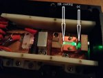
.......................................................So the input (left) end of the KTP has a High Reflector. Correct?
.
So the OC and AR 532nm coating manage the KTP?

Power Output: 5 mW 20 mW 100 mW 1 W 5 W
-------------------------------------------------------------------------------
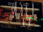
Pump Diode (1)
Maximum Power 100 mW 500 mW 1 W 10 W 50 W
TEC Thermal Power -- 1 W 3 W 30 W 150 W
Beam Correction <-- uLens or None --> Prisms <-- Fiber-coupled -->
Resonator (2)
Type <-------- Hemispherical -------> <--- Long Radius --->
Length 7 mm 15 mm 40 mm 80 mm 150 mm
HR Mirror (3)
Diameter --- --- --- 10 mm 15 mm
RoC --- --- --- 250 mm 500 mm
Vanadate:
Overall Size 2x2x0.5mm 3x3x1.2 mm 3x3x1.2 mm 3x3x3 mm 4x4x4 mm
Doping Level 3% 1% 1% 0.7% 0.7%
Side 1 Coatings HT@808nm HT@808nm HT@808nm HT@808mn HT@808nm
HR@1064nm HR@1064nm HR@1064nm AR@1064nm AR@1064nm
Side 2 Coatings AR@1064nm AR@1064nm AR@1064nm AR@1064nm AR@1064nm
TEC Thermal Power --- 0.5 W 1 W 4 W 20 W
KTP (4)
Overall Size 2x2x3 mm 2x2x5 mm 2x2x5 mm 3x3x7 mm 3x3x7 mm
Type <------------ Flux Grown --------> <-- Hydrothermal -->
Side 1 Coating AR@1064nm AR@1064nm AR@1064nm AR@1064nm AR@1064nm
Side 2 Coating AR@1064nm AR@1064nm AR@1064nm AR@1064nm AR@1064nm
Heater Power --- 0.5 W 0.5 W 1 W 2 W
OC Mirror (5)
Diameter 5 mm 5 mm 5 mm 10 mm 15 mm
RoC 10 mm 20 mm 50 mm 100 mm 200 mm
Side 1 Coatings HR@1064nm HR@1064nm HR@1064nm HR@1064nm HR@1064nm
AR@532nm AR@532nm AR@532nm AR@532nm AR@532nm
Side 2 Coatings AR@532nm AR@532nm AR@532nm AR@532nm AR@532nm

Great visual representation diachi, once again you amaze me of your knowledge. It makes 99% sense to me now in terms of the theory of operation. So it sounds like if I just replace the HRs with a 1123nm coating and the ARs with a 560nm coating and use LBO instead of KTP I should get my 560nm laser

") Hell, I'd say I'm not even 99% certain on a lot of DPSS design and theory. I'm sure I could do several degrees in these fields and still not have a complete, detailed understanding of how all of it works.
Hell, I'd say I'm not even 99% certain on a lot of DPSS design and theory. I'm sure I could do several degrees in these fields and still not have a complete, detailed understanding of how all of it works.
Nope - crystal coatings need to be correct too, so you'd need to change the crystals. Can't just swap the cavity mirrors. And in plenty of cases the HR mirror is coated onto the YVO4, so you can't change that without changing the crystal anyway. Most other YVO4 transitions (outside of 1064nm) are significantly lower gain than 1064nm so they are even harder to get lasing - making the coatings/alignment/optics quality/cavity design and temperature stabilization even more important.
The yellows may favour a different dopant percentage in YVO4 too - I don't know the answer to that. I'd need to do some digging.
PLN system instead of the orthovanadateProbably why Shalomeo uses a Nd:YAG + MgO
Since I feel pretty humbled by the vast knowledge of some of the members here I am going to spend a few weeks reading up on these interactions of laser light with crystals. I found this website where I am going to start my at-home research, Covesion Ltd. - Covesion Guide to PPLN, it seems like a lot of good current information on DPSS materials. Anyway I thought I'd share it with you as it relates to using IR pumped light to achieve independently assorted wavelengths.
The OC is kind of like the Brewster's angle of a gas laser.
No. The "brewster's angle" is not a device, it's an angle. A brewster window is a pane of glass (typically) situated at brewster's angle to prevent losses from this resonator window. The OC is a completely separate device. Look up the wikipedia page on these things. Relying on one or two sentences from an internet stranger isn't ideal for a topic like this.
Dopant % may have an effect in YAG too for Yellow vs Green. Not sure.
They'll be using YAG because YVO4 doesn't have the appropriate transitions (notably 1123 and 1319). YVO4 is suitable for 915nm,1064nm and 1340nm (summing of 1064 and 1340 would produce 593nm). 1064nm and 1319nm from YAG would sum to 588.9nm or 589nm if you're rounding.
Note: There will likely be other transitions but those are the major ones.
So you did that calculation via SFG right, so how do you know what crystal produces an SFG, SHG, or a DFG?