Welcome to Laser Pointer Forums - discuss green laser pointers, blue laser pointers, and all types of lasers

LPF Donation via Stripe | LPF Donation - Other Methods

Links below open in new window

ArcticMyst Security by Avery

Driving Multichannel AOTF

Joined
Jun 4, 2012
Messages
17
Points
3
I am ultimately trying to control an output spectrum's FWHM via an AOTF, i.e. a tunable bandpass filter. This is not for a laser show / projector system, but posting in this section seemed like the correct place to ask a few questions.

Out of my comfort zone of knowledge, so please correct me if I am wrong on any of this:
Most AOTF's have a very narrow FWHM for a given drive frequency, so in order to select a specific wavelength range, say between 400nm and 435nm, or 670nm and 685nm, you would need to then modulate the RF drive frequency going to the AOTF crystal - correct? If so, what type of modulation is needed to feed the VCO? My illumination source is a 450W Osram XBO Xenon bulb in a fiber coupled research arc lamp housing.

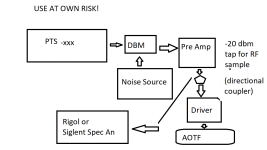
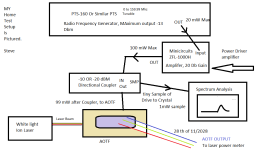
Here is a crude block diagram of what I believe would work. I have seen another control method where instead of an arbitrary waveform generator & bias tee, a variable voltage attenuator is placed after the VCO and is controlled by an additional supply voltage. Is there a reason for the two variations? diagram-1.jpg

Now, if I were to route a double pass through the AOTF to mitigate walk off - will that affect the drive frequencies?


Joined
Jun 4, 2012
Messages
17
Points
3
Have you done any further work since posting?

I have done a bit more research, but nothing concrete yet. I suspect there are two or three different methods to accomplish my original question. When studying commercially available drivers, there are a number of different manufacturers that sell a multichannel driver with X number of channels able to operate simultaneously. To me at least, this would indicate that they are using some form of what I originally posted in the block diagram - just duplicated for how many ever channels they are able to control.

The second method would be to sweep the drive frequency. This was the idea behind the original block diagram. Limited by the creation of harmonics, noise, and whatever speed you can sweep the frequency at. Unfortunately for the application that I am interested in using this technology, would require sweep times on the order of single milliseconds to hundreds of microseconds. A capable function generator from Keysight is something like $100,000-$150,000 (for their microsecond models.) At that point the $40k quote I received for brand new multichannel driver seems like a bargain... o_O

The third is to create some form of a phase locked loop and modulate the drive frequency itself. I really start to fall off the knowledge wagon at this point. I am 100% no expert in the field of RF. The easiest way to save on cost with this method is do everything via board mount components. I started to design a PCB to accomplish this, but even then the costs are still something like $1300. And this is just to control the AOTF. The design still relies on a decent function generator. And then the nice oscilloscope to measure everything etc. So at the moment I am just trying to save up some to experiment more. BLOCK-DIAGRAM-AOTF-DRIVER_export.jpg
 

LSRFAQ

0
Joined
May 8, 2009
Messages
1,155
Points
83
I work with / play with AOTF / Pcaom for a living. Whose crystal do you have? AA,Brimrose, Neos Gouch, Interaction?

You do NOT need a 3200$ Keysight for this.
There are tons of USB synthesizer cards on the market.

Typical max drive is 125 mW per channel , often a third of that, times 8 channels.

Given that acoustic travel time across the crystal limits the modulation rate, what are you trying to do?

Typically we use a surplus CATV broadband amplifier module [30-40$] from Phillips or Motorola, maybe TRW, to drive the crystal.

Again, what exactly are you trying to do,??

Steve
 
Joined
Jun 4, 2012
Messages
17
Points
3
I work with / play with AOTF / Pcaom for a living. Whose crystal do you have? AA,Brimrose, Neos Gouch, Interaction?

You do NOT need a 3200$ Keysight for this.
There are tons of USB synthesizer cards on the market.

Typical max drive is 125 mW per channel , often a third of that, times 8 channels.

Given that acoustic travel time across the crystal limits the modulation rate, what are you trying to do?

Typically we use a surplus CATV broadband amplifier module [30-40$] from Phillips or Motorola, maybe TRW, to drive the crystal.

Again, what exactly are you trying to do,??

Steve
I have a G&H - AOTF 2885-04, max output with 8 simultaneous channels is 3 W. Less than 375 mW per channel.

What I want to accomplish: be able to adjust a broad spectrum's FWHM to some specified range - wider than driving it with a single frequency. I know there are two ways, multiple simultaneous frequencies (correct?), or sweep between the two frequencies really fast.

Random wavelength access time is less than 1.5 microseconds. As long as the time between frequency steps in the sweep is greater than this, is the acoustic propagation still an issue?

My goal is to experiment with a hybrid/pseudo confocal microscopy setup, so accuracy somewhat matters. This is where I ultimately struggled in finding appropriate and affordable drivers or synthesizers. What are your suggestions for USB synth cards that can sweep in the microsecond range?

I have read a bunch of your posts here & you really are the expert on these things; so any and all help is greatly appreciated.
 

LSRFAQ

0
Joined
May 8, 2009
Messages
1,155
Points
83
Ok, there is also mixing a CW signal with a variable bandwidth noise signal as our machine does at work. Linear feedback shift registers with carefully chosen feedback taps generate the noise. It is applied to a doubly balanced mixer to mix with the carrier. We can tune from 4 to 40 nm in width. More details to follow, but a lot nicer then frequency hopping.

Steve
 

LSRFAQ

0
Joined
May 8, 2009
Messages
1,155
Points
83
Find yourself a working PTS-160 or PTS-250 or better on Ebay, the parallel port on the back is easy to program as it uses BCD, even better yet if it has front panel manual controls. 13 dbm = 20 mW, and believe it or not that will get you a faint image from the AOTF, if you look at a distant light bulb. The PTS also tunes at the speed of summer lightning. Direct Synthesis is very fast. THis is not what you would use for a laser show AOTF except for test, but for a lab setup it rocks.

www.programmedtest.com

Study this chart:


Until your used to measuring RF power and to prevent total burnout of your AOTF,

Start with say a used ZFL-1000H amplifier from Minicircuits on EBAY, 100 mW is enough to get started, if not enough for the project.
This lower power then rated idea protects your AOTF. Trust me, it is easy to overdrive the transducer with a hot amplifier. This usually has expensive consequences. You do not need the full rated 3 watts, these crystals work quite well below saturation.

Always make sure your power amp is rated well below the max power per channel on your AOTF. One Watt would be overkill.

Combining generators / designing shift register noise sources is a topic for another time.

See, can be done cheaply. I recommend having a Spectrum Analyzer around, ie Rigol DSA or better yet a Siglent. Heaven forbid you buy one of the 99$ ones on Ebay, works, but not optimal on amplitude calibration. One way or another you need an accurate, repeatable way of measuring RF power. 100$ Ebay RF power meters are not that accurate, hence the suggestion of a spectrum analysis system.

A directional coupler lets you sample say -20 dbm of your RF into your SSA, if you have never used a spec an, put a 10 dbm attnenuator on its RF input. If you get the Siglent with the Tracking Generator, you may use it as a driver to learn from.

RF gain is cheap using MMIC amplifiers and 3 resistor SMD RF pads as attenuators.

The ARRL RF handbook is your friend.

A common beginner's mistake is to add Dbm without converting. Dbm don't directly add, you have to convert to power, sum the power (or loss) and convert back to Dbm.

Note to laser show hobbyists who will read this post, PCAOM are driven with a different scheme using multiple oscillators and summing networks, this post is not for you.

Good Luck,
Steve
 

Attachments

  • nicely nicely AOTF.png
    nicely nicely AOTF.png
    24.6 KB · Views: 3
Last edited:

LSRFAQ

0
Joined
May 8, 2009
Messages
1,155
Points
83
Minicircuits is your friend.

These work, and they are not the only product on the market:


An Arduino or Pi has more then enough IO pins for you to drive a PTS., 32 Khz steps are probably too fine for your application, 64 or 100 Khz is probably close enough.


I love my Siglent SSA3021X, the tracking generator is included free, and if you dont care about speed, the TG can drive the amplifiers.

Gets decent reviews: Rigol DSA700

Steve
 
Last edited:

kecked

0
Joined
Jun 18, 2012
Messages
929
Points
63
Steve related but different answer can I cascade aom used as choppers to shorten a pulse lenght? Was thinking chop with the first and gate with a second or even third using a delay line. I get the power isnt high but I’m after pulse length more than power. Was looking to use on output of a Ti:Saph 3900s. To spoof being nanosecond pulsed. In my app I don’t need the high peak of say a q switch.
 
Joined
Jun 4, 2012
Messages
17
Points
3
I love my Siglent SSA3021X, the tracking generator is included free, and if you dont care about speed, the TG can drive the amplifiers.

Gets decent reviews: Rigol DSA700

Steve

Thank you very much for the detailed responses. I just purchased the ARRL RF handbook, figured its best to learn more before throwing money at something else. Next will be a quality spectrum analyzer.

In your diagram what exactly is the driver you had in there? With the proper frequency and power levels - isnt that technically all that is needed to drive the AOTF's (or did my brain completley forget something)?

Lastly; when you mentioned driving the amplifiers directly from the tracking generator, is that through the DBM like in this diagram? Or does the tracking generator just remove the need for the PTS and DBM completley, with the tradeoff being you are limited by the speed of the spectrum analyzer. BLOCK-DIAGRAM-2.jpg

BTW, with a business / non personal email address you can actually get a free account with Lucidchart and still have like 80% of all the block diagram features. Pretty cool software.
 

LSRFAQ

0
Joined
May 8, 2009
Messages
1,155
Points
83
Your cell specs 375 mW per channel max. That is certainly an overdriven situation, it should saturate optically much below that.

From Minicircuits App Note 40, 26 Dbm is 398 mW. https://www.minicircuits.com/app/AN40-012.pdf

So the used 30$ ZFL-1000H on Ebay is 100 mW or 20 Dbm when saturated. That is enough to get started when driven by the PTS-160 Family at -13 Dbm, or 20 mW. You are an RF beginner, so I'm trying to limit your max Transmit power until you know enough RF skills to know how to protect a 3000$ AOTF Crystal.

If your Spectrum Analyzer has the tracking generator, they will probably output 7 Dbm (10 mW) or more from the tracking output. Normally this is a RF output is centered on the instantaneous frequency of the sweep, and on mine, (Siglent SSA series) this can be fixed to one frequency while sweeping out a wider spectrum, independent of Analyser tuning. So in theory, for testing, you can use the TG output to get started with testing with your AOTF. You just need more amplification to get to your target power. Within limits, you can stack Minicircuits or other brand 50 Ohm impedance amplifiers in series.

In other words, for quick tests, you could skip buying the PTS, but this is highly NOT recommended.

In the diagram, I have a Directional Coupler module for checking forward or reflected power from the AOM, thus ensuring I'm not overdriving it.

My SA is a Siglent SSA3021X Plus with the TG as a free option, included. So basically the TG is a frequency synthesizer.


Rather expensive Directional Coupler that lets you measure, S12, S12, parameters for calculating VSWR, reflected and forward power, and seeing your spectrum and spectral bandwidth. It samples the signal:


cheap used one:


See https://learnabout-electronics.org/Amplifiers/amplifiers13.php for the math.

1669691561762.png

Steve
 
Last edited:

LSRFAQ

0
Joined
May 8, 2009
Messages
1,155
Points
83
Your cell specs 375 mW per channel max. That is certainly an overdriven situation, it should saturate optically much below that.

From Minicircuits App Note 40, 26 Dbm is 398 mW. https://www.minicircuits.com/app/AN40-012.pdf

So the used 30$ ZFL-1000H on Ebay is 100 mW or 20 Dbm when saturated. That is enough to get started when driven by the PTS-160 Family at -13 Dbm, or 20 mW. You are an RF beginner, so I'm trying to limit your max Transmit power until you know enough RF skills to know how to protect a 3000$ AOTF Crystal.

If your Spectrum Analyzer has the tracking generator, they will probably output 7 Dbm (10 mW) or more from the tracking output. Normally this is a RF output is centered on the instantaneous frequency of the sweep, and on mine, (Siglent SSA series) this can be fixed to one frequency while sweeping out a wider spectrum, independent of Analyser tuning. So in theory, for testing, you can use the TG output to get started with testing with your AOTF. You just need more amplification to get to your target power. Within limits, you can stack Minicircuits or other brand 50 Ohm impedance amplifiers in series.

In other words, for quick tests, you could skip buying the PTS, but this is highly NOT recommended.

In the diagram, I have a Directional Coupler module for checking forward or reflected power from the AOM, thus ensuring I'm not overdriving it.

My SA is a Siglent SSA3021X Plus with the TG as a free option, included. So basically the TG is a frequency synthesizer.


Rather expensive Directional Coupler that lets you measure, S12, S12, parameters for calculating VSWR, reflected and forward power, and seeing your spectrum and spectral bandwidth. It samples the signal:


cheap used one:


See https://learnabout-electronics.org/Amplifiers/amplifiers13.php for the math.

Steve
 

Attachments

  • AOTF TEST.png
    AOTF TEST.png
    36.3 KB · Views: 2

LSRFAQ

0
Joined
May 8, 2009
Messages
1,155
Points
83
Directional Coupler split ratios

3 and 6 are worthless for your project, 10 is barely useful, 20 is even more useful if not perfect , 30 and 40 will be too expensive and kill your SA

Coupling ValueSplit Ratio (%)
3 dB50/50
6 dB25/75
10 dB10/90
20 dB1/99
30 dB0.1/99.9
40 dB0.01/99.99
Attenuation Quick Reference:

Power In (mW) Power Out (mW) Attenuator Value
10 9.0 -0.45 Db
10 8.0 -0.98 Db
10 6.0 -2.2 Db
10 5.0 -3 Db
10 2.5 -6 Db
10 1.0 -10 Db
10 0.1 -20 Db
10 0.01 -30 Db
10 0.001 -40 dB

RF Gain Quick Reference:

Power In(mW) Power Out (mW) Gain Db
0.01 1.0 20
0.1 1.0 10
1.0 1.0 0.0
1.0 1.5 1.76
1.0 2.0 3.0
1.0 3.0 5.0
1.0 5.0 7.0
1.0 7.0 8.45
1.0 10.0 10.0
1.0 12.5 11.0
1.0 15.0 11.6
1.0 20.0 13.0
1.0 25.0 14.0
1.0 30.0 14.8
1.0 35.0 15.4
1.0 40.0 16.0
1.0 50.0 17.0
1.0 60.0 17.8
1.0 70.0 18.5
1.0 80.0 19.0
1.0 90.0 19.5
1.0 100.0 20.0
1.0 150.0 21.8
1.0 250.0 24.0
1.0 500.0 27.0
1.0 750.0 28.5
1.0 1000.0 30.0
1.0 1500.0 31.0
1.0 1750.0 32.5
1.0 2000.0 33.0


Top